This is a quick how-to guide on making your own ethernet or patch cables for the desired length you need.
I will start by listing all of the things you will need to make this cable.
I prefer to use Klein tools, but other brands will work just fine. I have worked with many different brands, but the quality seems to be better when used daily. If you’re a hobbyist the less expensive option may be a better choice. Also, you may notice that I am using Cat5e cable, these steps will work with Cat6 varieties as well.

I will do step by step on how to complete the process using the T-568B method.
Step 1. Cut the cable to the desired length. I went with about 15 meters. The maximum length you’d want to use is 100 meters, any longer than that will cause performance issues or cable loss.
.

Step 2. Strip the cable, using the ring tool. With this specific tool, you snap it on and spin it 360 degrees and it scores the cable without damaging the twisted pairs. I recommend stripping around 5cm or 6cm. By doing this it will make it easier to line up the colors in the right order.

Step 3. If you bend the cable back and forth a couple times, it will break the jacket of the cable where you scored it. You will need to cut the pull cord off.


Step 4. Untwist the pairs and line them up in the right order. In this picture you will see the T-568B wiring method. The order is as follows; white/orange, orange, white/green, blue, white/blue, green, white/brown, brown. Click here for the explanation of T-568B wiring method. As explained by CBT Nuggets.


Step 5. By trimming off the extra of the exposed pairs we can get it to approximately 1.5cm. This will allow the conductors to touch the end of the connector so they will be crimped properly. It may take a couple times of trimming the conductors to get it right. If you cut them too short, they won’t reach the pins inside the connector and if they are too long the jacket will be sticking out of the connector causing a weakness in the cable.

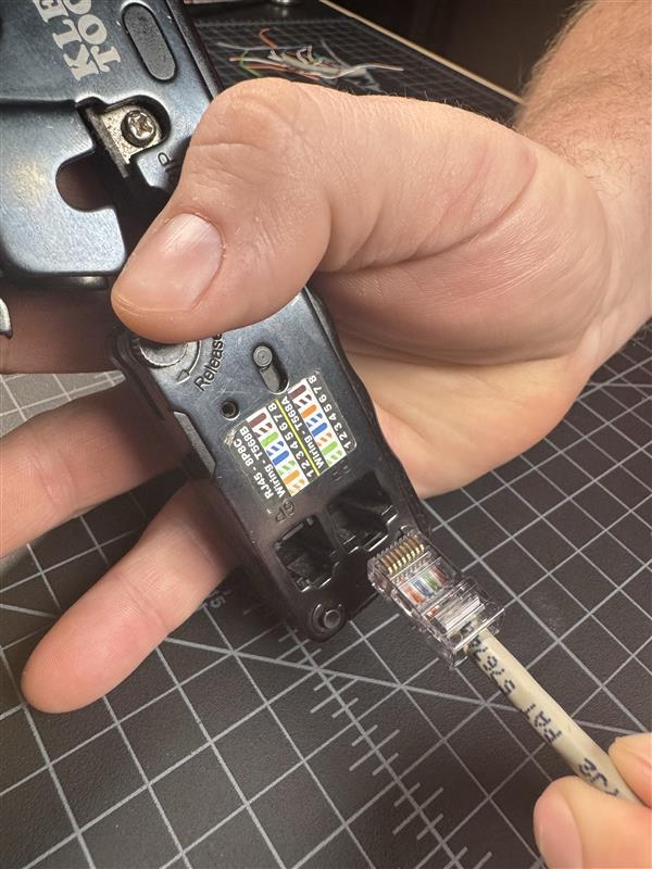
Step 6. Line them up and slide into the RJ45 connector. Notice the jacket of the cable is inside the connector as well, this is to make the connector stronger by crimping the jacket. If you look close at the connector, you will see grooves that each conductor goes into. Once again, you should verify the colors are in the correct order. The prong on the connector should be facing down so that pin 1 is on top.


Step 7. Crimp it with the RJ45 crimper. There are many types of crimpers on the market, but this specific one made by Klein is my preference because it ratchets and locks meaning you have to squeeze it completely or it won’t release. This ensures that you have a proper crimp, not too much or not enough. I usually squeeze it a couple times just to make sure.

Step 8. In this step we will need to inspect the ends to make sure they look right. Notice in the first picture the colors all match up right with the T-568B wiring method. The second picture show the ends of the connector. Notice the colors show and you can see the shiny ends from the copper.


Step 9. Test the cable to make sure it is working properly. With this tester it shows pair for pair testing meaning it is pin 1 to pin 1, pin2 to pin 2, etc. It will work for testing most cable types including a crossover cable. In the pictures below, the first picture shows a verified T-568B method cable. In the second picture it shows a verified crossover cable.


Step 10. Congratulations, you have completed the correct process for making an ethernet cable!!
For high level detail check out this other post below.