I have acquired several excelitas “CALIPILE SMD ADAPTERBOARD TPIS 1S 1385” from DigiKey and have begun prototyping a sensor capability but ALL of the devices are not responding as they should. Either the documentation is wrong or these parts are bad. I have verified our connections many many times.
Here is the basic issue:
Note: we are not using a Excellitas UNIVERSAL DEMO KIT WITH USB as we are involved in Ultra Low power testing of this device for battery backed design
- The evaluation board provides for a PH-6 connector that conveys I2C and power connections.
- In accordance with datasheet we pull up the SDA line to 3.3v. No pullup on SCL however.
- using 3.3v Vcc
- connected to a IOT uC: ESP32 breakout pcb
- we conduct an I2C bus scan with 13ms clock stretching (slow!), using a digital scope see no response from the adapter boards. We have side-by-side other I2C device to compare proper connections and view.
I purchased 4 of these “CALIPILE SMD ADAPTERBOARD INCL. TPIS 1S 1385”
as well as two TPiS 1T XX8X adapter boards and two TPIS 1T 1086 L5.5.
None of the TPIS-1S-1385 adapter boards work. We have double checked our wiring and used good anti-static practices (humid Alabama weather) to no avail.
We need to talk to a (Excellitas) technical rep now. Thanks
Please offer constructive help getting to someone who could help. Thanks
Hi timbopoise,
Welcome to the Tech Forum.
I would highly recommend that you first evaluate these modules with the “UNIVERSAL DEMO KIT WITH USB CONNECTION & CABLE” (DK part # 1601-1010-ND), as it allows one to both verify functionality of the sensor board and test the features of the sensor.
However, for immediate trouble shooting, the first thing I note is that you DO need a pull-up on the SCL line as well, as noted in paragraph 3 on page 7 of the datasheet. Also be sure your address matches how you have configured A0 and A1, as this can be easily overlooked.
David_1528,
Thanks for your speedy response and suggestions.
Actually I did put a pullup on the SCL line as well.
I’ve had a focus on Excellitas Calipile sensors and have found DigiKey difficult to work with–you have to know exactly
what you are looking for: search for “calipile” you don’t get all of the products one might be looking for; search for
“Excellitas” you don’t get any results; search for product numbers from their datasheets-they don’t translate to DigiKey db.
Oops! I’m bitching sorry.
I did finally find that there was a “universal demo kit” board and bought it and it’s on the way. I’m a Linux shop to know
I supposed I have to get Windows laptop ready…Grrrr!. But I should not have had to do this since we
are talking very basic I2C IO, schematic, datasheet, etc. $100+ just to verify the adapter board works and then back to more
direct interface setup and testing.
I’m simply trying to do an I2C bus scan to detect the address. This has always been reliable for my other i2C devices. The
Calipile never responds.
Thanks again.
Hi timbopoise,
Regarding issues with the website, please give that feedback using that tab that rides along the right side of the screen on our website. The more feedback the web people see there, the more effective it becomes (much more so than internal critiques). If you can explain why these are failures, that can also help (i.e. should recognize the extra “L” in vendor name, ensuring we include marketing series names, associating variations of part numbers, etc.).
I don’t disagree with with your point regarding buying a board to simply verify functionality in principle, but over the years, I have seen customers spend countless hours banging their head and eventually concluding they had bad hardware, when in fact it was some simple thing which was overlooked. Having that test board will quickly verify whether a board is functional or not, saving many dollars worth of time. Then one can focus on why it isn’t working in their application, knowing that they aren’t dealing with bad hardware. Additionally, careful study of the hardware and software of the demo board often can give important clues on that front.
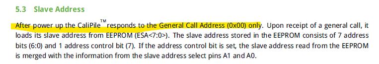
An additional thing I noticed on page 8 of the datasheet that you probably saw, but which surprised me, was that the sensor must first be addressed after power-up with the “General Call Address” of (0x00), which then triggers it to load it’s slave address from it’s EEPROM, which is then used for all subsequent communication. If that were missed, that could certainly cause problems.
Best regards
David_1528,
OM-Goodness, you may have hit on it: the requirement to issue a general call address of address 0x00 may be the trick.
I will heed your suggestion regarding feedback. Thanks.