Created by Scott Schmit, last modified by Robert Nelson on Apr 05, 2016

Purpose
The purpose of this page is to demonstrate usage of the built-in CAN controller of the ATmegaxxM1 family of microcontrollers. This project achieves CAN communication between multiple ATmega32M1 devices using STK600 development boards. CAN Libraries for ATmegaxxM1 devices in Studio 6 are provided as well.
CAN Background
The Controller Area Network (CAN) protocol is a robust serial communication protocol commonly used in automotive and industrial applications. CAN networks use a shared bus to connect all nodes in the network. There is no Master-Slave relationship in the CAN protocol. Instead, all nodes have access to the same bus, and bit-wise arbitration of each message is used to determine priority and avoid bus-collisions. Each message contains a unique identifier along with a priority level. If two nodes try using the bus simultaneously, the message with higher priority will “win” bus access while the lower priority message will abort. CAN communication is applicable in networks that require relatively low data rates (1Mbps or less), but very high immunity to EMI and temperature effects. The diagram below illustrates how multiple nodes are connected to the shared bus in a CAN network.

Notice how there is a CAN transceiver in between the bus and each CAN controller. The CAN bus is comprised of two differential signal wires CANH and CANL. The CAN transceivers are necessary to convert the single-ended Tx and Rx lines of the controller to differential signals CANH and CANL. The following image displays a scope capture of the CANH and CANL lines during a CAN transaction.

Reference
For readers that are new to CAN communication, it is strongly recommended to research the CAN communication protocol before attempting to realize a CAN network in hardware.
- AN713 - Controller Area Network (CAN) Basics.pdf (106.4 KB) - Controller Area Networ (CAN) Basics
- sloa101a.pdf (261.6 KB) - Introduction to the Controller Area Network (CAN)
- atmegaxxM1_Datasheet.pdf (6.6 MB)
- STK600 User Guide.pdf (2.2 MB)
- ATA6660 - datasheet.pdf (232.5 KB)
- CANLIB for AT90CAN
Project Brief
This project will demonstrate how to configure the built-in CAN controller within an ATmega32M1 device. We will cover the necessary hardware connections and describe the application code of two types of nodes. This project will also explain how to connect the ATmega32M1 controller to the actual CAN bus.
This project implements a 3-node CAN network. Two nodes behave as Sensor Nodes which collect local information. The third node behaves as a Hub Node, receiving sensor data from the Sensor Nodes and presenting the information to the user.
The STK600 was used as the development platform for this project. The STK600 allows the user to evaluate any AVR microcontroller using a socket and routing-card system. It breaks out every port of the microcontroller and includes 8 user-LEDs and 8 general purpose buttons. The STK600 also provides an on-board CAN transceiver (ATA6660) to connect the ATmega32M1 to the CAN bus.
Atmel provided a CAN software library for the AT90CAN device family in Atmel Studio 4. That same CAN library was used for this project, but was modified for the newer ATmega32M1 device in Atmel Studio 6.
Project Requirements
- ATmega32M1 - 8-bit AVR microcontroller with integrated CAN controller. One is required for each Node.
- ATSTK600 - Complete evaluation board for all 8 and 32-bit AVR microcontrollers. One is required for each Node.
- ATSTK600-SC10 - 32-pin TQFP socket card for STK600. One is required for each Node.
- ATSTK600-RC22 - STK600 Routing Card for ATmega32M1 microcontroller. One is required for each Node.
- 30-9506-77 - DB9 serial cable for connecting the CAN bus. The 10-pin ribbon cable that comes with the STK600 kit can also be used to connect two nodes. Since 2 Sensor Nodes were used in this demo, both cables were needed.
- Atmel Studio 6 - Free firmware development software from Atmel.
System Clock
The STK600 provides a slide switch for selecting the clock source of the AVR under evaluation. On the STK600, the user has the option of using the internal RC oscillator of the AVR, an External Clock Source, or an external Crystal as the System Clock source. The STK600 provides a socket for inserting a crystal. It also provides an on-board programmable oscillator which was used as the clock source for this project. The clock source setting on the slide switch was set as EXT. Due to the bit-synchronization process in the CAN protocol, the System Clock must be at least 8x greater than the desired CAN baud rate. The CAN Libraries used in this project support baud rates of 100, 125, 200, 250, 500, and 1000 kbps. In order to fully support all of these baud rates, the minimum system clock for the AVR is 8MHz. The programmable oscillator was set to 8MHz through Studio 6 Device Programming interface. The user must also clear the CLK_DIV8 fuse within the ATmega32M1 through Device Programming.
Configure STK600 Programmable Oscillator

- Mount the AVR to the STK600 using appropriate socket and routing cards (STK600 Socket Guide).
- Connect the on-board programmer/debugger to the AVR device using the appropriate ribbon cable. For this project, the ISP header was used to program the ATmega32M1 device. Make sure the VTarget and Reset headers are each shorted with a jumper.
- Connect the STK600 to the PC using the provided USB cable. Ensure the STK600 is powered on.
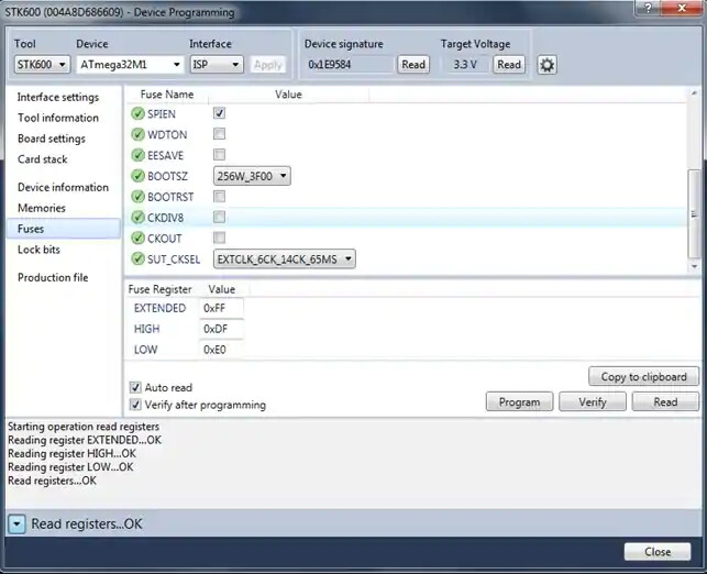
- In Atmel Studio 6, navigate to Tools → Device Programming.
- Select STK600 as the Tool.
- Select ATmega32M1 as the Device.
- Select ISP as the Interface and click “Apply”.
- Towards the top of the Device Programming dialog, click “Read” under Device Signature. The device’s serial number should display. If not, try adjusting the ISP clock in the Interface Settings tab (200 kHz works well).
- Select the Board Settings tab.
- If not already done, make the Target Voltage 3.3V by using the slider or by typing in the text box (ARef0 and ARef1 can be left alone).
- Set the Clock Generator to 8MHz and click “Write” (generated value may be slightly off).
- Select the Fuses tab.
- Set the SUT_CKSEL fuse to “EXTCLK_6CK_14CK_65MS” (may need to scroll to view the fuse).
- Deselect the CKDIV8 fuse.
- Click Program.
- Close the Device Programming Dialog.
- Power down the STK600 board.
- Set the Clock Source slide switch to “EXT”.
- Re-connect power and the AVR should be running at 8MHz using the programmable oscillator as the System Clock source.

Due to the strict timing requirements of the CAN protocol, it is not recommended to use the internal RC oscillator within the AVR device as the System Clock source. The accuracy of the internal RC oscillator is highly dependent on temperature and supply voltage. Therefore, in practice it is recommended to use an external crystal as the System Clock source for a CAN node.
Hardware Connections
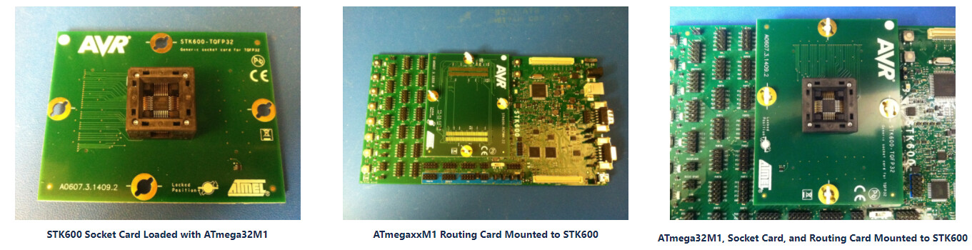
The ATmega32M1 was mounted to the STK600 using the socket card (ATSTK600-SC10) and the routing card (ATSTK600-RC22).
PORTC[3:2] on the ATmega32M1 are the CAN[Rx:Tx] pins. The STK600 includes an on-board CAN transceiver (ATA6660) for converting the single-ended Rx and Tx lines to differential signals needed on the actual CAN bus. However, the user needs to physically connect the CAN controller to the CAN transceiver using jumper wires. PORTC[3:2] pins were connected to the CAN Rx/Tx header on the STK600 using one of the 2-wire jumpers included in the STK600 kit.
PORTB of the ATmega32M1 was used as the 8-bit LED control port. The PORTB header and the LED header on the STK600 were connected using one of the 10-pin ribbon cables included in the STK600 kit.
On the Hub node, one of the general purpose buttons (SW0) was used to trigger a request for data from the sensor nodes. PORTC[7] was configured as a digital input (pullup enabled) to read the status of SW0. SW0 was connected to PORTC[7] using the 10-pin headers on the STK600 and a single jumper wire.

The STK600 provides a standard 10-pin header for the CAN bus, as well as a DB9 connector for the CAN bus. Either (or both) can be used to connect different CAN nodes together. A DB9 cable was used to connect Sensor Node 1 to the Hub Node while Sensor Node 2 was connected to the Hub Node using one of the 10-pin ribbon cables included in the STK600 kit.


The CAN bus must be properly terminated to ensure the differential signals CANH and CANL display the correct voltage characteristics (RL shown in Figure 1 of CAN Background Section).
The length of cable used to connect the nodes will change the voltage characteristics of the CAN bus. To compensate for these effects, the STK600 provides a “Term” header (next to the DB9 connector) that can be shorted to add resistance between the bus lines.
The “Split” header allows the user to insert a filtering capacitor to choke out any common-mode noise on the CANH and CANL lines.
Also, a “Slope Control” header is used to prevent EMI from affecting the bus lines. This is connected to a standby pin on the CAN transceiver (see ATA6660 datasheet for details). Therefore, to keep the transceiver in active mode, a jumper must be applied to either side of the “Slope Control” header.
The user may or may not need to short the “Term” header and/or the “Split” header. It all depends on how long the CAN bus is and what the baud rate is set to. For this project, the “Term” header needed to be shorted, but the “Split” could remain open and still maintain bus integrity. In a noisier environment, the “Split” header may have been needed to achieve necessary noise immunity. The user must always short one side of the “Slope Control” header to enable bus transactions for that node.
Application Code
ATmegaxxM1 CAN Libraries
The AT90CAN software libraries provided by Atmel for Studio 4 were modified and used in Studio 6 for this project. The libraries provide some low-level CAN macros, as well as some higher level functions that are implemented by the main application. The modified CAN libraries for ATmegaxxM1 are provided below.
Zip containing all files:
- ATmegaxxM1 CAN Libraries ATmegaxxM1_CANLIB.zip (13.3 KB)
Individual Files:
Example Application
There are 2 types of nodes in this project - Sensor Nodes and a Hub Node. The Sensor Nodes collect local data and transmit the results to the Hub Node which then displays the information to the user. The collector / sensor example application within the CANLIB zip folder was modified for use in this project. The example projects used for this demo are provided below.
- Hub_CAN_Ex.zip (79.8 KB)
- Sensor_CAN_Ex.zip (77.2 KB)
Testing the Example Code
- Configure the Hub Node as described in the Hardware Connections section.
- Connect the Hub Node to the PC using the provided USB cable.
- Setup the System Clock as described in the System Clock section.
- Program the Hub Node using the Hub_CAN_Ex project provided above.
- Configure a Sensor Node as described in the Hardware Connections section.
- Connect the Sensor Node to the PC using the provided USB cable.
- Setup the System Clock as described in the System Clock section.
- Connect the two nodes together using a DB9 cable or a 10-pin ribbon cable.
- Ensure both nodes are powered up (press Reset button on each STK600 to ensure program start-up).
- Press SW0 on the Hub Node. The ID Tag of the Sensor Node and a test byte should display on the LEDs of the Hub Node.
You should notice LED0 flash on the Sensor Node when a message response is requested by the Hub Node. - Configure, connect, and program the 2nd Sensor Node.
- Press SW0 on the Hub Node again. You should see the ID Tag and test byte of each Sensor Node display on the LEDs of the Hub Node (1-second pause between ID’s).
Comments from the Author
The CAN communication protocol is used in many applications due to it’s high reliability. The reader is strongly encouraged to fully research the CAN protocol before jumping into the provided example code. The CAN Libraries provided in this project were modified from the CAN Libraries written for AT90CAN devices. I hope this project was helpful to you. I encourage you to fully explore all of the functions within the provided CAN Libraries. I challenge you to add functionality to the example projects. Maybe add some sort of error reporting or additional message types. If you have any interesting breakthroughs, I would love to hear about them. I hope you enjoy working with Atmel’s AVR CAN controllers!
- Scott
For questions or feedback about information on this or any other page, please go to the TechForum: TechForum
