The other day I was tasked with a project from a co-worker of mine. He was given an older CB radio he said would not power up and wondered if I could have a look at it. I verified the symptom and sure enough, it was “dead” and did not power on as stated. So, off with the covers on the unit to see what’s up. A pretty common problem I remembered would happen is the user would hookup the radio with reverse polarity. The design of the radio included a diode, who’s operation was to provide reverse polarity protection. Basically if you hooked up the radio the wrong polarity, the diode would conduct (D23) and it would blow the 2 amp fuse (F201) in the power cord. This was a pretty typical circuit used for the power input.
Naturally the fuse would blow, but the user would not always replace the fuse with the same current rating. Typically they would replace it with a higher current rating. So, with the radio still hooked up backwards for power, now instead of the fuse blowing, a circuit trace on the printed circuit board would blow. The result is as shown in the image below.
Many times besides the copper trace being blown on the circuit board, the reverse polarity diode would also short out and would have to be replaced too. But in this case, we lucked out and the diode tested good in circuit.
So, now we have to fix this open trace. First step is go use a small precision screwdriver (blade type) to remove the coating on the copper trace on the board. Gently scrape away the coating on the trace to expose the bare copper as shown here.
Clean both ends of the open trace.
Now apply some flux to prep the copper for tinning (which is simply a thin layer of solder on the copper pads)
Once you have the copper traces tinned, with a piece of solid wire (also referred to as bus bar wire), solder one end of the wire to the first half of the open trace.
And a little bend with a needle nose pliers to get it to line up with the other half of the trace…
Solder the other end of the wire to the other half of the open pattern.
Trim the wire back to the solder and clean with some flux remover…
And the repair is made
Final step was to check if the radio worked, and it powered up after the repair. This procedure can be used anytime you have to repair a printed circuit board trace. Whether is a burned trace such as this, broken trace on a cracked board, or maybe even a trace you have lifted and broken in a repair attempt .
More Tech Tips you may be interested in:
Removing thru hole components from two sided circuit boards
Easily Remove Surface Mount Components from PCB
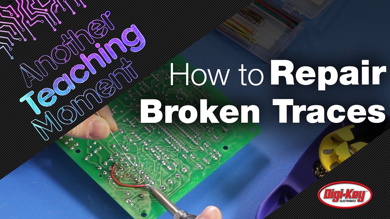
Here’s a video take on the topic if you would like to check it out.


