Background
Backup generators are handy things, but they’ve got their drawbacks. In recent years, a large warehousing concern having several substantial gensets experienced a spate of equipment failures associated with load transfer events, with numerous pieces of equipment connected to a 3-phase, 480V feed experiencing failures. Among these failures were a number of AC-DC converters used to power production-critical infrastructure. The original supplies in this application had been in service for roughly 20 years with limited downtime, and considering their age, operational importance, and hard-core obsolescence cemented by a series of corporate acquisitions, it was thought that a phased replacement program was warranted in order to maintain reliability of service.
What didn’t work: (part one)
Curiously, the old supplies continued to plod along, while all (as in 100%) of the new supplies that were being installed were failing, typically within about a year of installation. Understandably, answers were sought: this wasn’t what people had in mind when they decided to start replacing these power supplies in the interest of reliability…
The supplies initially selected as replacements for the original equipment devices were a factory-configurable type, consisting of a modular chassis providing functions of common interest (bulk rectification & filtering, power factor correction, etc.) in which one or more modules that convert an intermediate DC bus voltage to one or more lower-voltage final outputs can be installed. The units in question were fitted with a pair of output modules configured to have a combined output capacity of 40A at 65.3VDC, or just over 2.6kW.

Figure 1. An example of the replacement supplies that didn’t last.

Figure 2. Outer inscription noting internal fuse values and warning of need for a chassis earth connection due to high leakage currents.

Figure 3.: The supply parted into its two halves.

Figure 4. Panel removed, showing fuse chamber
During a postmortem examination of one of these failed supplies, the first clue as to the cause of failure was evidence of arcing between the leads of what appeared to be a three-phase rectifier array, composed of a half-dozen Vishay VS-HFA16TB120PBF diodes, which are rated for 16A and 1.2kV and come in a TO-220 package All three of the 10A, 500V AC line fuses (having a 5x20mm format and shrouded in heat-shrinkable tubing) near the power entry point to the supply had been blown along with what appeared to be a DC link fuse situated further into the supply, and a number of the other diodes in the rectifier array were found to be faulted as well. Replacement of the diodes in this array along with the fuses restored this supply to basic operation; comprehensive testing was not undertaken, since the device would not be returned to service in any event.

Figure 5. Input half of supply with fuse chamber removed. Path of input power in 3-phase AC format across board is shown by red arrow, post-rectification in green.

Figure 6. The input rectifier array (right of the toroids) which failed. Photo taken post-repair.
Of the three identical (failed) supplies examined, all exhibited this same fault pattern, along with a large uninterruptible power supply not discussed here which showed similar symptoms suggesting an input overvoltage event as the proximate cause of failure.
Tracing the path of input power through the device, the external terminal blocks feed power into a sequestered chamber in which the internal fuses are found, shrouded in supplementary heat-shrinkable insulation, along with the first 4 of no less than 10 filtering component stages, involving common-mode chokes, non-coupled inductors, and X- (between phase) and Y- (phase-ground) capacitors. Though the circuit was not fully reverse-engineered, it appears that the final beige film capacitors and litz-wound toroid inductors in the polyphase power path prior to the rectifier array are part of a boost-mode power factor correction scheme.
An array of 1kV-rated FETs opposite the final toroid bank from the input rectifer bank is accompanied by a few more of the Vishay diodes, which appears to feed into a bulk capacitance built from a half dozen 450V/220uF electrolytic capacitors (Rubycon QXW series) in a 3 parallel x 2 series configuration, for an aggregate of 330uF that can operate at up to 900V. In parallel with each trio of these caps is what looks like an MOV: there is no apparent over-voltage protection incorporated into the supply up to this point.
Though the numerous filtering stages the input power passes through as it makes its way through the supply might well afford some protection against fast voltage transients by smearing them into into lower-amplitude events of longer duration by the time they hit the rectifier array, the lack of over-voltage protection seems to render this design vulnerable to lower-frequency events by route of input rectifier failure. This should be considered an observation rather than a conclusion; this design was not studied in comprehensive detail, and it’s possible that this interpretation of observed behaviors may be incorrect.
Though they do carry an adequate voltage rating and were not observed in any of the three cases examined to have opened in a manner which rendered the device irreparable or which required the intervention of external protection mechanisms, the internal fuses on this device do appear to benefit from the supplementary insulation with which they were equipped; the remains therein were rather, well, crispy in some instances… Given a larger sample size, the appearance of more violent failure effects would seem likely, making internal fusing with a higher interrupt current rating a potential opportunity for design improvement. Fuses of this type are commonly rated to interrupt only a few hundred amperes at rated voltage, which isn’t all that hard to exceed given a 480V source.
Aside from these observations, examination of this supply left a generally favorable impression, at least with regard to component selection: the temptation to save a penny here and there through the use of products from low cost sources seems to have been avoided.

Figure 7. Bottom view of input rectification board.

Figure 8. Closer view of fuse cage, post-repair. 5x20mm fuses were/are shrouded in heat-shrinkable tubing within a sequestered chamber of the device to reduce collateral damage when fuses open.
What worked before (and still does)
The original equipment power supplies in the application were rated to output up to 38A at 65.8VDC, from either a 480V or 230V 3-phase supply. This unit is of a more monolithic and integral character, reflecting more of a purpose-built design philosophy than the modular concept embodied by the others.

Figure 9. A power supply which provided twenty years’ service under application conditions which resulted in a 100% failure rate of the previously examined design within a two year service period. As a result of this analysis, the original supplies were refurbished and remain in service.

Figure 10. Interface panel of the power supply in figure 9.
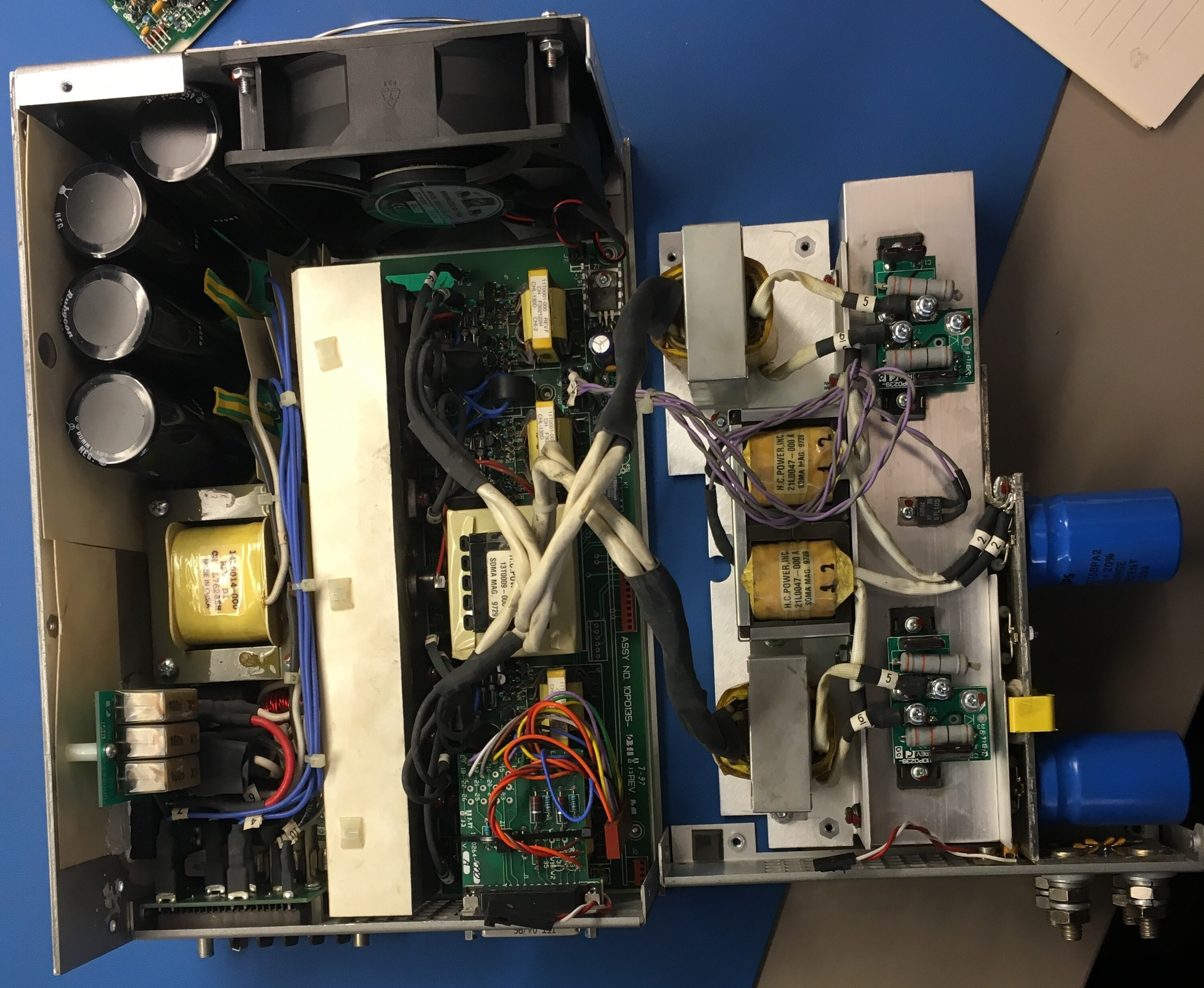
Figure 11. The opened supply separated into its two major internal segments.
Opening one of these supplies for sake of comparison (there were twenty used, in a distributed massively-parallel redundant system) offered immediate insights on potential reasons for their superior service longevity. While not directly contributing to this longevity, the selection of internal fuse components suggests that the protection components were not an afterthought. Rated for 14A/500V, these comparably beefy 5AG format (0.406" x 1.5") devices are rated to interrupt up to 10kA at 500VAC. These were fitted into holders rather than being soldered into place.

Figure 12. Input section showing fuses, bridge rectifiers, and shrink tube-protected MOVs. X-capacitors for snubbing diode recovery are also shown.
Shortly thereafter in the input chain is the likely reason for these supplies’ service longevity: a trio of metal oxide varistors (MOVs) shrouded in heat shrinkable tubing and connected across the input phases, directly adjacent to the input rectifiers. These rectifiers were of a common 3510 class, having a nominal 35A capacity and listing a 1kV peak reverse voltage (700V RMS). Datasheet characterizations for devices of this type suggest that these figures include a bit of margin to their actual poof voltage, which occurs at roughly 1.1 to 1.2kV. The MOVs selected for use were reportedly a V480LA80BP, rated for a maximum operating potential of 480VAC and having an indicated clamping voltage of 1.16kV at a 100A current level, which is quite reasonable. Though bit of margin between the nominal line voltage and the rated operational maximum for the selected MOV would seem desirable to guard against the chance of conduction at the AC line peaks, a higher rectifier voltage rating would be required to avoid a resultant loss of protective effect, and precedent seems to indicate that the chosen device rating is adequate. The prevalence of non-power factor corrected electronic loads has a tendency to flatten the peaks of AC utility waveforms, providing what is perhaps an unexpected benefit in this specific case.
Tangentially, opening the cover on this long-serving supply was a bit like opening a time capsule from 1997. Surface mount? What’s that?

Figure 13. The control section of the OEM power supply.
What didn’t work (part two)
In any event, replacing a pool of power supplies that had offered minimal troubles over 20 years with devices that exhibited a 100% failure rate within 2 years of installation is not the path to securing reliability of one’s production-critical infrastructure. The supplier of this infrastructure was advised to this effect, having offered the ill-fated supplies as updates, and a different alternative was sought. The second candidate offered took on a different form; rather than using two separate diode OR-ed supplies at each cabinet position in the system, a single converter chassis containing multiple modules was selected by the equipment vendor. The installation would not be a simple direct replacement; the old supply cabinets would need to be removed, and new ones installed. The effort involved would be substantial, and require that the powered equipment be taken out of service for a time. In light of the installation costs and potential consequences of supply failure, the decision was made to take a peek inside these second-attempt replacement supplies, to see what sort of input protection they were equipped with before proceeding with the installation.
As a result, that installation never took place.

Figure 14. The second-try supply with cover removed, showing the modules within.

Figure 15. A bulk input rectification & filtering module from the second-try supply.
The second-try supplies contained two modules which take in three-phase AC and output a bulk-rectified, coarsely filtered DC, and four other modules which convert the resulting bulk high-voltage DC into an isolated 65V output. A schematic for the input modules developed during their examination is at right. The input rectifiers are of a fairly generic 5010 integrated bridge style, rated for a maximum 50A average rectified current and 1kV maximum reverse voltage.

Figure 16. Schematic for bulk rectification module developed during its examination.

Figure 17. Diode bridges on the second-try supply’s input rectification module
While these bulk rectification modules did incorporate overvoltage protection components, their implementation was found to be decidedly unsatisfactory. The MOVs used were marked S20K625, indicating a TDK/EPCOS product with a varistor voltage of nominally 1 kV, with upper and lower limits on that figure of 0.9 and 1.1kV respectively. This specification describes the potential that must be applied across the device to cause a small current to flow, usually about 1 mA, which in terms of nastiness is comparable to one stereotypically polite Brit inadvertently bumping into another in queue. Oh, terribly sorry suh, how clumsy ohv me…

Figure 18. One of the MOVs present on the input rectification modules.
Substantially more voltage will appear across one of these MOVs when clamping a transient with some current behind it; closer to 1.6kV in fact when clamping a 100A transient. It appears that the designer in this case may have simply selected an MOV with a rating equal to that of the rectifier it was supposed to protect without paying heed to what the ratings actually mean, and allowing the MOV some space in which to work. Whatever protection the chosen MOV could provide to the rectifiers in use is something of a marginal question, hinging on where individual components fall within their allowed tolerance.

Figure 19. Datasheet excerpts for the MOVs and bridge rectifiers used, with data for the parts in question highlighted.
Unfortunately, that question is rendered moot by the manner in which those MOVs are connected. They’re connected not between the input phases in delta fashion, but from each input phase to a common junction point, wye style. It appears that provisions on the board existed to facilitate a connection of this common point to the neutral conductor of a 3-phase wye service, but the connection had been deliberately omitted.

Figure 20. Illustration of Delta- and Wye-connections. Two series-connected MOVs must conduct in the latter case to clamp an over-voltage event applied between any two phases.
As a consequence of this choice in connectivity, input overvoltage events are imposed across two of the MOVs in series rather than one. Since the resulting 2kV varistor voltage (the point where MOVs just start to provide a protective effect) is double the maximum reverse rating of the input rectifiers, it’s highly probable that those diodes would fail during an over-voltage event before the protection mechanism ever kicked in.
But wait, there’s more…
The input fuses with which this supply was equipped were of a 3AG (1/4” x 1 ¼”) format and rated for 250VAC, at which potential fuses of this type commonly have an interrupt rating of a few hundred amps.
The voltage and interrupt current ratings on a fuse characterize the maximum potential in a circuit that can be driving a fault and the maximum magnitude of the resulting fault current (respectively) that a fuse should be called upon to interrupt if it’s to be expected to do its job. Failure of a fuse to do its job in this context implies the formation of an arc between the fuse endcaps, through which fault current can continue to flow with surprising ease until interrupted by some other influence. Because of this effect, fuse voltage ratings are not additive and the use of 250V rated fuses in an appliance intended to be powered from a 480V source is not appropriate.

Figure 21. The under-specified fuses used in the second-try supply.
This second attempt at securing a replacement power supply was arguably a worse result than the first; not only did it lack effective input overvoltage protection, its inadequate internal fusing created a increased likelihood of internal overcurrent protection failure in the probable event of supply failure due to over-voltage events. Failure of internal overcurrent protection would defer responsibility for interrupting a fault to protection mechanisms at the cabinet or service panel, which have progressively higher trip points and thus a higher risk of Bad Things Happening due to sustained arc faults. These occur when the impedance of a fault in a system is high enough that the resulting current flow isn’t high enough to cause a protection device to open, allowing the fault to buzz, burn, weld, melt, ignite, and otherwise do damage for an extended period of time.
Realizing that this alternative supply also was not a route to securing system reliability, they were not installed. Instead, a preventive maintenance program for the existing, suitably-protected supplies was instituted. In pairs, without interrupting production, they were removed for service consisting of a careful cleaning and replacement of components subject to wear and aging: fans, electrolytic capacitors, optocouplers, and MOVs. Cost of parts and labor per cabinet was about $500, contrasted with approximately $3000 for the first attempt at replacement, and an estimated $8,000 per for the second.
The moral of the story? Circuit protection matters, and when it REALLY matters, it can sometimes be a good idea to open the hood and see for oneself what’s underneath.