We use cookies to provide our visitors with an optimal site experience. View our privacy notice and cookie notice to learn more about how we use cookies and how to manage your settings. By proceeding on our website you consent to the use of cookies.
Many thanks! I test it! not that I do not trust, but I searched and searched on the datasheet without finding anything, you could indicate me or make a screen where this is written
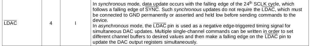
It is stating that if the LDAC is tied to GND, then the latch that is between the SPI block and DAC is transparent and DAC output is updated at SYNC edge.
It may be a good idea to test it yourself to confirm the desired operation.
TI’s FAE may also help you there.
Unfortunate to hear.
I think there are still things to try. Let’s make it work!
Allow me to ponder this a bit (it’s already late night this part of the world)… Meanwhile, I wonder, could you provide a bit more information:
What DAC value did you write to the chip and what output voltage you got (or actually, how the operation differs to 8552)?
Is there a chance to get a photo or schematics of the test circuit?
If the great people at Digi-Key have ideas, kindly give a shout.
The register format for 8562 and 8552 is not 1:1. That is, 8552 cannot be controlled with the same software blob as 8562. I am afraid that you will need to write a new driver for the DAC.
Take a peek on example like this (Note: is for Arduino):
First of all, my apologies for providing pointer to 8552 example code instead of 8652. My bad.
I’ll take a look into your code tomorrow morning. Meanwhile, encouraging everyone to provide a solution.
OK. Took a look at the driver code.
I do not have STM32 SDK, thus cannot test the code.
However, attempted to modify the driver to suit for DAC8562, with the following remarks:
The code is not compiled nor tested. No guarantee given that it works.
Tried to make as few changes as possible.
The original code has methods Dac::Write and Dac::Update. Not sure how the author is using them.
The Write method does not test if SPI frame send is complete. Added a wait loop.
The Update method does not test if SPI frame send is complete. Did not include a test for frame overlap (yet).
There are 8 extra clocks in each DAC access due to 16 bit SPI frame (I’d use 8 bits frame instead…)
Due to external 2.5V reference, the DAC8562 needs to be configured to use that. Added code for it in Dac::Init(). Remove, if does not work.
Disabling LDAC pin functionality with a register write in Dac:Init(). Make sure LDAC pin is grounded!
Note: Channels are not updated synchronously, thus you may observe minor phase shift. Maybe does not matter as I guess they are oscillator outputs.
Let me know if this does not work or works only partially.
Hi Heke, i test it, but not all work,now it seems more controllable, the sounds stand out better, but still not as they should, it seems that they are still digital and not completely analog
Good to hear that you got something out.
It sounds like the output gets distorted.
According to the schematics, there is quite a lot of gain in the output stage.
In addition, it seems that the original DAC’s output range is from 0 to Vref, where as
in my code version the range is set 0 to 2xVref. I’ve attached below a modified version of the code
where the range is set to 0…Vref. Test with it and tell what you get. dac.cc (3.3 KB)
OK, so we’re almost there. I’ll look into the code.
Meanwhile, could you inform what kind of measurement instruments do you have at hand
(multimeter, oscilloscope?) and what SDK you are using to compile the code and flash the MCU?
BTW, modular synthesizer sounds fun.
If still getting distorted output, I wonder, could you take a picture of the oscilloscope display showing a typical signal? That would help to understand the source of the problem.