VHDL Code for Tutorial
blinking_led.vhd (1.6 KB)
Introduction
This introduction to the Efinix Efinity software (version 2021.2.323.1.8) walks through creating a simple project using the Trion T120F576 Development Board. The use of other development kits is analogous. Topics include starting a new project, code entry, making pin assignments, compilation, installing the necessary driver, and programming the board.
Creating a New Project
To create a new project, select File → Create Project…, and the Project Editor Wizard launches. Enter a project name and location as shown in Figure 1. Also specify the target FPGA and speed grade. The Trion T120F576 Dev Board includes its namesake FPGA in a I4 speed grade.

Figure 1. Entering the project name, project location, FPGA family, device and speed grade
Next, click the Design tab to specify your design files. Click on the Add design file icon as shown in Figure 2. Select the blinking_led.vhd file provided above and click Open.
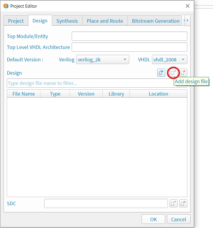
Figure 2. Adding design files
Specify the Top Module/Entity and the Top Level VHDL Architecture, in this case the “blinking_led” entity and “behavior” architecture within the blinking_led.vhd file, respectively, as shown in Figure 3. Click OK.

Figure 3. Specifying the design
Pin Assignments
To make pin assignments, select Tools → Open Interface Designer. Once it opens, select Design → Show/Hide GPIO Resource Assigner. In the Design Explorer section in the lower left, right click on GPIO(0) and click on Create Block as depicted in Figure 4.

Figure 4. Creating GPIO assignments
The blinking_led design has two ports: clk and led. In the Block Editor in the lower right, type “clk” in the Instance Name field and press the Enter key. The result is shown in Figure 5.

Figure 5. GPIO instance created
Repeat the process for the led port. Right click on GPIO(1) and click Create Block. Type “led” in the Instance Name field, press the Enter key, and then select output from the Mode dropdown since this port is an output port.
To assign an FPGA pin to a port, click in the Resource column of the GPIO Instance View that corresponds to the port and type the name of the FPGA pin. The Trion T120F576 Development Kit has a 50 MHz oscillator on pin GPIOR_186. Assign this to the clk instance. Assign pin GPIOB_RXP04 (LED0 on the kit) to the led instance. See Figure 6.

Figure 6. Pin assignments
Click File → Save. Then click Design → Check Design to verify there are no issues. Close the Efinity Interface Designer window.
Compilation
Select Flow → Synthesize to begin compiling the design. By default, the Efinity software has an automated compilation flow such that this step will synthesize the design, then immediately proceed to place and route the design and generate the bitstream files. These processes can be performed independently by toggling this feature off (the icon in the upper right corner of the dashboard). A green checkmark appears on each process icon on the dashboard once that process completes. Figure 7 shows the dashboard after the entire compilation finishes.

Figure 7. Compilation complete
Programming the FPGA
Provide power to the Trion T120F576 Development Kit, plug it into the computer via the USB cable, and switch it on by toggling SW17.
Installing the USB Driver with Zadig
If you have not already installed the libsubK USB driver, do so now.
Download and open the Zadig software (available here). Choose Options → List All Devices. Turn off Options → Ignore Hubs or Composite Parents. Select the Trion T120F576 Development Board (Interface 0) from the dropdown. Select libusbK(version) next to Driver. Click Replace Driver. Next select the Trion T120F576 Development Board (Interface 0) from the dropdown. Select libusbK(version) next to Driver. Click Replace Driver.
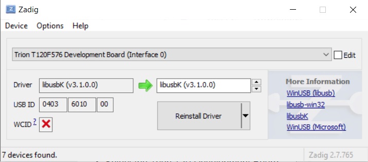
Figure 8. Zadig software for libusbK driver installation
Configuring the FPGA
Open the programmer by selecting Tools → Open Programmer. If the proper USB driver is installed and the target development kit is plugged in and powered on, then the USB Target field should populate with your target board.
Click on the Select Image File icon as shown in Figure 9 and open the blinking_led.bit file. Select JTAG from the Programming Mode dropdown. Click the play button icon to the right of this dropdown.
Once the programming completes, LED D0 on the Trion T120F576 Development Kit blinks once per second.

Figure 9. Programming the FPGA
Conclusion
This introduction to the Efinity IDE from Efinix using their Trion T120F576 Development Kit demonstrates the essential steps to create a simple project with these tools.