Frustrated with tag sprawl in your PLC?
Stop asking what tags a block touches. Instead, think in term of data structures.
Instead of thinking in terms of individual tags, think in terms of User Data Types (UDT) and Databases (DB). As a loose analogy, treat each UDT as an object. We then construct blocks to operate on the object(s). The technique:
-
Forces a function level grouping of the tags into a DB (UI, process, memory). With the caveat that we didn’t just move the tags to a larger junk drawer with the DB.
-
Identifies all tag interaction (the contract) from within the blocks IO interface. This acts as a skeletal shadow greatly reducing the need to look into other parts of the program to discover tag meaning. It also reduces the chances of missing a tag especially as the program grows and tag names start to look the same across HMI and process control.
-
Simplifies and shortens naming conventions within a given block. The reduction in dot notation levels is helpful, especially when working with arrays as it eliminates deep nesting of the tag names. No more rummaging through the junk drawer.
-
With tags packed cleanly within data structures, we eliminate the PLC equivalent of spaghetti-code. It’s not a question of jumps and loops, but data coupling through clarity of tag use.
If done correctly, this ordered structure can save time for everyone who reads the code.
This article is part of the DigiKey Field Guide for Industrial Automation
Location: Program It → Data Structures (UDT/DB)
Difficulty: ![]() System Integrator — difficulty levels explained
System Integrator — difficulty levels explained
Author: Aaron Dahlen | MSEE | Senior Applications Engineer, DigiKey
Last update: 06 Mar 2026
Introduction to the Block Interface Contract
The block interface contract is a technique that describes the interface surface between the PLC’s data and the function block(s). We could think of the blocks as methods, and the DB as the memory being operated upon.
Note that IEC 61131 is not an Object-Oriented Programming language. However, the clarifying concepts are important and apply directly to the code encapsulation described in this article.
The Failure Defined
A block is broken if we cannot see what it is and is not connected to it without digging through the code. Failure to address hidden dependencies increases the time required to read the program thereby increasing down time. They also make it harder to make future changes. The hidden dependencies are difficult to locate.
Make your blocks copy/paste safe.
For example, an HMI may have its own tag table. Other tag tables may be added for distributed I/O, or process control.
It’s all about global variables. Think of this as a failure mode of scaling without structure. Increased program size demands attention to program organization. Regarding globals:
-
Use globals for physical IO.
-
Don’t use them to reach out to random memory locations from within a block thereby violating the block contract. It’s a hidden dependency that will bite in the future.
Bottom line: Without clean organization, a large PLC project becomes unmaintainable.
Do I need to know this?
Yes, as this visualization will help you understand the libraries provided by the various OEMs. For example, the OEM for an IO-Link field device may include a library with both programs and UDTs. You are instructed to incorporate the UDTs into a DB. The OEM supplied programs then operate upon the DB.
The classic way to program a PLC and why it gets messy
This is a question of program scaling where the classic tag-based PLC programs follow a similar pattern:
-
Global tags are used for I/O
-
Local tags are used within a Program Organizational Unit (POU)
-
We are forced to use global tags as we cross POUs
Problems of Scale
This becomes problematic for larger programs as the associations are hidden. In fact, a block may quietly reach out to many databases with no apparent linkages until we study the tag names. We visualize this as an HMI octopus reaching out to many different locations.
This becomes maddeningly complex with increased program size. Consider what happens when we add another section to the machine. While the same instantiated blocks are required, we can’t just copy and paste. Instead we must drill into the block(s) and make sure each tag is appropriately linked to the appropriate tag in the appropriate DB. Miss a tag and the machine will break, or worse yet, there will be a latent bug.
Demonstration of the UDT within DB Technique for a Network Interface
As an example, let’s construct a PLC to external database interface (e.g., MySQL or TimescaleDB):
-
The PLC is in control of the Ethernet interface.
-
A two-tiered message system is used:
-
The priority buffer processes, alarm events and user actions. This priority buffer will retain messages in the event of a network failure. It is also a recognition that the PLC’s retained memory is limited. In this example, 34% of the retentive memory is consumed for 50 messages.
-
A secondary buffer is used to hold the cyclic process data to prevent the flood of data that would otherwise overwrite the priority buffer in a network failure.
-
The ladder logic is presented in Figure 1. Network 1 contains a pulse per second and a pulse every 3-seconds stimulus. Network 2 contains the producer blocks for the primary message queue. The first block will place the message Pulse per second into the queue while the second will add Pulse every three seconds into the queue.
Note that each block’s InOut interface is “bolted” to the PriorityBuff ring buffer that lives within the MSGBuffs DB. This FB_PriorityQueue block is a lightweight block that can be instantiated anywhere we want to send a status message to the DB e.g., pushbutton, HMI activation, fault status etc.
Technically, this InOut linkage is a pointer to a clearly defined memory structure. Using microcontroller-based thinking, we have constructed a function with a pass-by-reference interface. Instead of multiple pass-by-value we operate on the live object; with all the benefits and heartaches that entails.
Don’t even think about using interrupt-driven code. Two message writers simultaneously operating on an unlocked DB is a recipe for corruption.

Figure 1: TIA Portal Ladder Logic showing two producers feeding the "MSGBuffs".PriorityBuff ring buffer.
The Message Data Type
The UDT for the message type is included in Figure 2. There are three fields including:
-
SequenceNum: This field is used to identify a unique message. It provides a measure of truth to the external database; missing messages are identified as discontinuities between message fields. -
DTLStamp: This is the PLC system time (Date Time Long) for the moment the message was developed. -
Payload: A simple 80-character string is used for this demonstration.

Figure 2 Type message contains three fields.
The Ring Buffer Data Type
There are eight fields for the ring buffer as shown in Figure 3 including:
-
RunningSeqNumber: This location maintains the sequence number for the messages. -
Size: This is a hard coded (magic number) for the number of elements in the ring. This is a hardware limitation of the S7-1200 requiring us to define memory size at compilation. Note that a S7-1500 includes an array[*] operator that would have simplified the code. -
NumMSGInBuffer: This is for convenience and monitoring purposes. It may be used as a proxy for network health. -
HeadPointerandTailPointer: These are the classic ring buffer pointers for the message producer (HeadPointer) and consumer (TailPointer). -
OverFlowCount: This is an unfortunate reality of the limited memory. It counts the number of times when old data is overwritten. -
Status: The status field is another diagnostic tool. It allows codes to be used such as network health or “buffer at 80%”. -
MSG: This is an array of messages (see Figure 2) for a description of the data type.

Figure 3: Priority ring buffer type definition.
Instantiation of the Ring Buffer in a DB
In the final step, the ring buffer data type is instantiated into a DB called MSGBuffs. The debug window output is shown in Figure 4. Here the windows have been opened to show the ring buffer variables and the contents of MSG[0].
Note:
- The
PriorityBuffinstantiation is configured to be retentive. This will preserve the message types across a PLC power failure. This consumes 34% of the retentive memory for the Siemens CPU 1215FC.
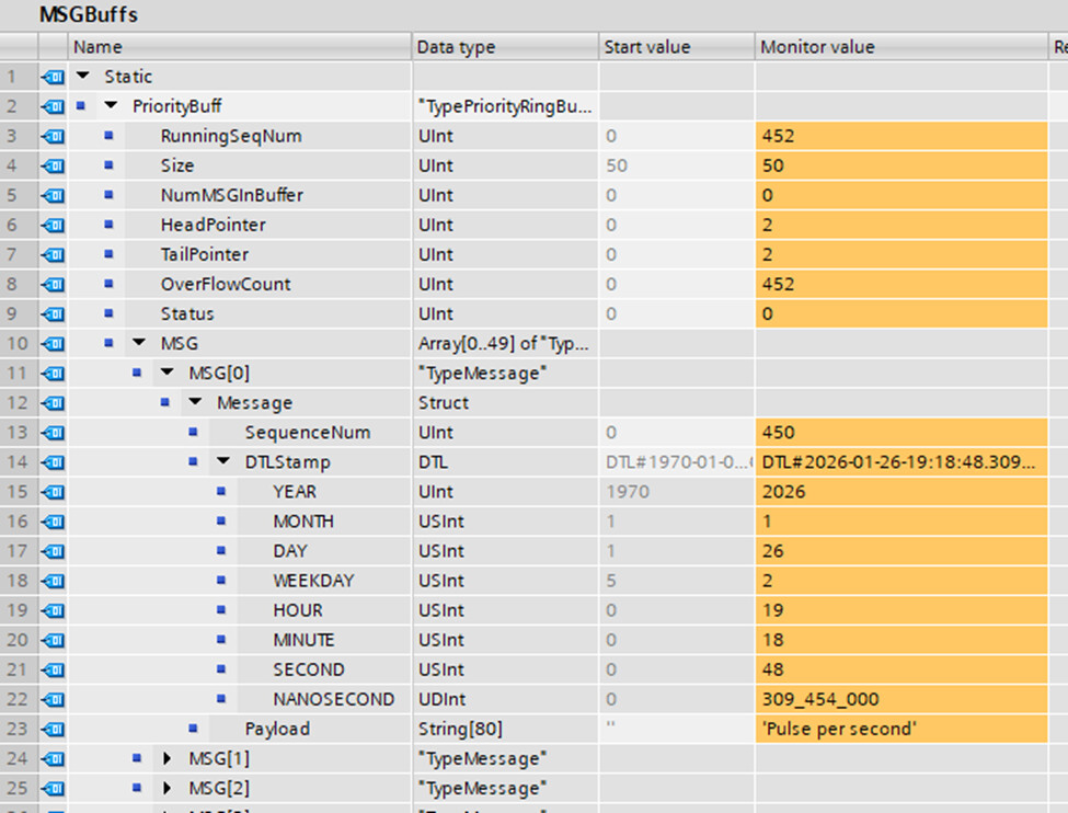
Figure 4: The Ring buffer type is instantiated in a DB.
Use of the Instantiated Data from Within a Program
Figure 1 shows how to use the instantiated UDT from within the DB while Figure 5 presents the blocks I/O interface and the first two networks. In this example, we use the tag name IO to reference the DB. It’s short, descriptive, and easy to read, especially when we use indexing. For example #IO.MSG[#IO.HeadPointer].Message.SequenceNum places the running sequence number into the appropriate message slot within the ring buffer:
Benefit of using an instantiated UDT from within a DB
We now arrive at the most important statement of this article:
All block inputs and outputs are defined through this interface.
It’s a clean interface that respects encapsulation. There are no hidden references to PLC tags or other DB tags. In fact, we didn’t even need to open the block as Figure 1 provided a complete roadmap. Instead of thinking what tags the block requires, we flip the thinking and ask what object the block is operating on.
In this network-centric application we can separate the producers (Figure 1) from the consumers (not shown). In all cases each block operates on the UDT instantiation(s) within MSGBuffs.

Figure 5: Function block description with emphasis on the InOut interface.
Technician Considerations
There are two competing points to consider with regards to your workforce:
-
This programming style deviates from the typical textbook example presented to technicians and engineers.
-
The programs are simplified and the relationship between individual blocks are immediately obvious at the top level.
Clarity, simplification, and overall navigation are preferable to meeting conventional expectations. All things considered, this should reduce system down time, reduce bugs, and simplify future modifications.
Troubleshooting
To explain this code, think of the ring buffer as a post office:
-
HeadPointer: Location for the new package
-
TailPointer: The next package to be retrieved by the mail truck (first in first out)
-
NumMSGInBuffer: Number of packages ready to be picked up
-
OverFlowCount: Number of spoiled packages shredded in the bit bucket
Warning signs: If all is operating correctly, the number of messages in the buffer will be low and the shredder count will be low. If the external network is slow or unavailable the buffer will fill up.
Parting Thoughts
The code described in this article is like a flight recorder for the PLC with external storage. In this article we describe the interface used to gather the messages into a central memory location. In a future article we will describe the transport mechanism.
We shall end as we started:
Stop asking what tags a block touches. Instead, think in term of data structures.
Sincerely,
APDahlen
 Continue Exploring Industrial Control Systems
If this discussion was helpful, you may also want to explore:
 DigiKey Navigation
- Full Catalog: Industrial Control & Automation
 Related Foundational Articles
- PLC Response Time Explained: Hardware Interrupts vs the Scan Cycle
- Beyond Specs: Soft Requirements for Selecting the Right PLC
- Why Potentiometers Become Nonlinear When Loaded (PLC and Microcontroller Inputs): Introduction
About This Author
Aaron Dahlen, LCDR USCG (Ret.), is a Senior Applications Engineer at DigiKey in Thief River Falls. His background in electronics and industrial automation was shaped by a 27-year military career as both technician and engineer, followed by over a decade of teaching.
Dahlen holds an MSEE from Minnesota State University, Mankato. He has taught in an ABET-accredited electrical engineering program, served as coordinator of an electronic engineering technology program, and instructed military technicians in component-level repair.
Today, he has returned to his home in northern Minnesota, completing a decades-long journey that began with a search for capacitors. Read his story here.