We use cookies to provide our visitors with an optimal site experience. View our privacy notice and cookie notice to learn more about how we use cookies and how to manage your settings. By proceeding on our website you consent to the use of cookies.
Hello,
I am new here. I am fairly certain I have the right sub forum to ask about which resistor will suit the circuit without failing and ruining the sanken outputs ( no longer manufactured)
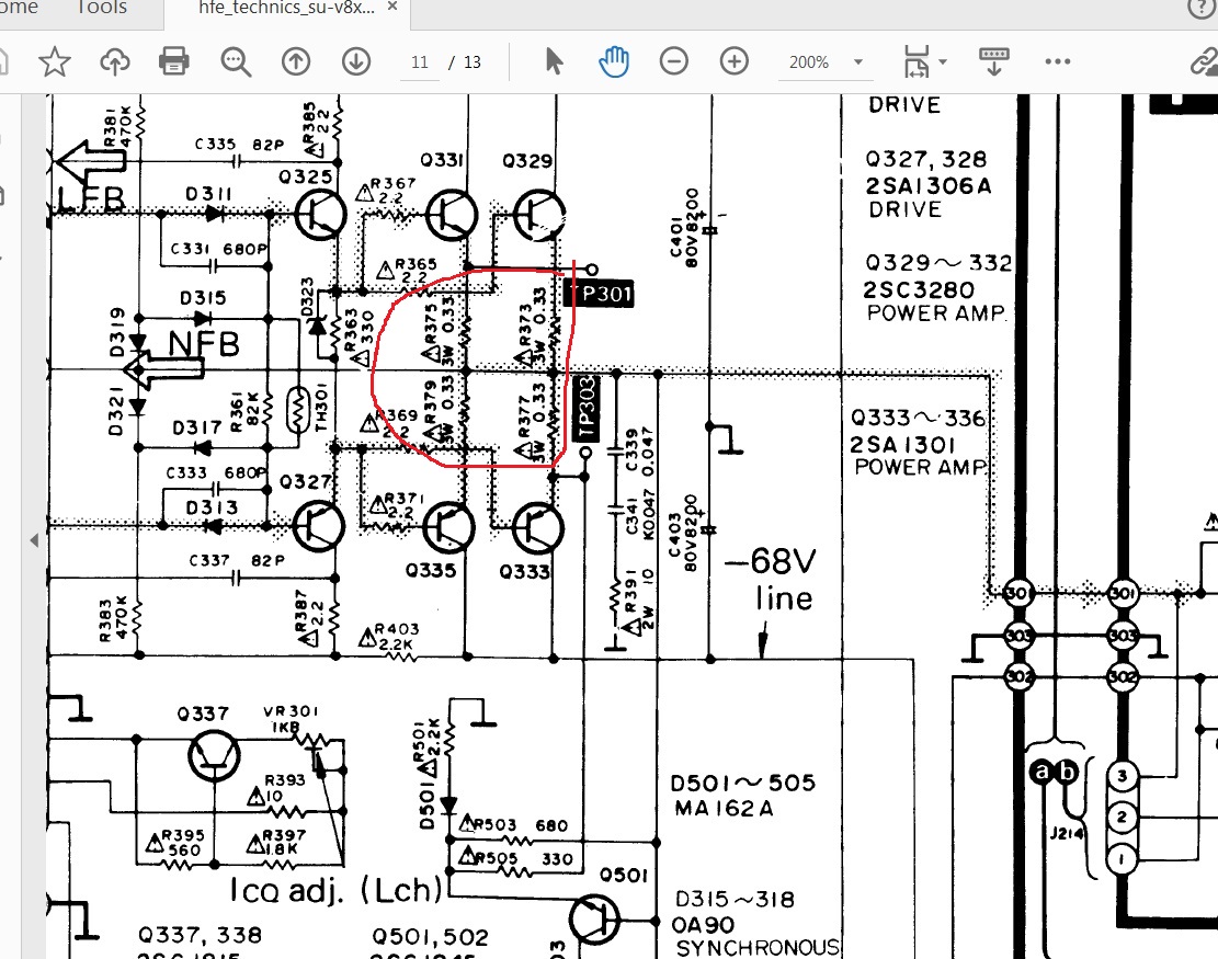
I have uploaded part of the circuit in the amplifers power section - Technics SU-V8X from the 80s.
I am upgrading the power supply capacitors, which a friend has also done 8200 to 12000uf. He used the high PPM resistors like the original. I was wondering if there would be benefits going for some lower ppm resistors?
Original part 3W 0.33 ohm (330mohm) 10% tolerance and assume the ppm would have been high.
Digikey part number:
A137401-ND = resistor like old 10% tolerance 300PPM 5w
0.33W-5-ND Yageo wirewound 100ppm 5% tolerance, not sure if its 100ppm or higher
MRA05-.33-ND - vishay low TCR, ? 25c before derating 4W
The problem with the lower ppm part is that they are rated at 25 vs 70c derating. Another friend sugguested maybe 7 - 10w to compensate for this?
Welcome to DigiKey TechForum. Please take a look at 696-1055-ND. This is 330mOhm, 5W, 1% tolerance, 20ppm/K. Physical size may be a bit bigger however: 0.250" Dia x 0.500" L (6.40mm x 12.70mm)
Lower PPM the better, as the resistance will fluctuate less with temperature change if you are worried about thermal runaway in the amplifier outputs. The 330mOhm resistors are feedback/swamping resistors placed in series of each output.
The feedback resistors provide a form of negative feedback, increase impedance seen from the input, but mostly minimize the effects of temperature on the emitter-base junction resistance, and also to absorb any simultaneous turn-on voltage between the two transistors -as in AB ampifiers both transistors will be in a state of conduction part of the time, resulting in more heat dissipation through the transistors, and exacerbating the problem of forward voltage drop change in the emitter-base junction of the transistors.
The feedback resistors in the emitter legs of the push-pull transistor circuit helps reduce this vicious cycle of thermal runaway, so going with a higher power rating, higher temp, lower PPM, and tighter tolerance in these is a good move.
@PaulHutch Hello Paul, Thank you for the reply and help in the explanation of the higher tolerance resistors that were in place and available, though the old ones could have been Koa or something as its a Technics amplifer. Thank you Sam
@Ryan_2724 Hello Ryan, Thank you for the reply and help and explanation. Its a Technics amp with newclass A, so it runs pretty warm. Last i used it , it went into protection, had periodic heating issues for a few years - re fault trimpot (going bourns in my order). The Riedon sound great resistors and less in size than the old large original ones. I feel less worried about thermal runaway from what you explained. Thank you Sam
@Ryan_2724 Hello Ryan, i wrote to Riedon as per product sheet stating to ask for ppm under 1ohm. The ppm/c is 120? is that still okay. I dont know the quality of the Taiwanese brand Yageo, but the part number (if correct from the product pdf sheet) the ppm would be 73ppm? PNP5WVJT-73-0R33. Tolerance is higher at 5%.
YAG1219CT-ND - Cut Tape (CT) is the part number.
it depends on the environment, but 100ppm is good option, but there is some that are tighter and more that vary the resistance more. " PPM per deg C " means the R increases per degree Celsius.
Thanks Robert for the reply and help. I found Riedon website had a great example about low ppm and resistance change being less with lower ppm. The environmont these are going are at the amplifiers outputs (emitter resistors) so, the area gets pretty warm as they are Technics new class A technology.
Sorry about the double post.
I am working out the resistors derating
The Rideon suggested by Ryan, its ppm is 120ppm for the values i need 0.33 and .47.
Say the amplifier runs at 100c. That means 0.00297 resistance change? going by Riedon site example
Other options with vishay also available. I would mount the resistors high so there is airflow and not flush with the pcb.
First, for a part rated as 100ppm/°C (100ppm = 0.01%, or 1/100 of 1%), if the temperature were raised 100°C, it would change value by only 1%. So, it’s an irrelevant spec for any resistor with a tolerance greater than 1%.
Second, looking at your schematic, it seems to me that the symmetry of the four resistors is more important than their absolute values, as the intent is to have the output as close to the “middle” value with equal voltage dropped across each resistor. Assuming this is correct, as long as the four resistors are of the same make and model, and that they are placed in relatively close proximity, so as to all be at approximately the same temperature during operation, their respective resistances will tend to track with each other as they warm up, thereby keeping their ratios pretty constant even if they have relatively poor ppm ratings. This means that as long as all four resistors have the same temperature coefficients, even if they aren’t particularly tight (meaning low ppm values), they will tend to do what they are designed to do in your circuit.
Therefore, focusing on “ppm” rather than other specifications is not necessarily going to give you the best solution. It would be better to be looking for relatively tight tolerance (probably 1% or better), high quality resistors rated for at least 2x the maximum expected power they are likely to see in circuit.
@Ryan_2724 Thank you Ryan for the link. It was an interesting read, and helped me understand TCR more.
@David_1528 Thank you David, for the reply and help, and explaining. The original parts going by the service manual were 5% tolerance and 3 watt, as for ppm not idea, but being an amp from 1984, maybe ppm values were higher.
I should be looking at 6w or 10w? the Riedon at 5w and 1% seem a good choice, as currently limited in choice with either 15w or 20w resistors (these look like transistors - could require heatsinks). The UB5C, should be fine? Its little more than 3w (almost 2x),
Are the resistors in question demonstrably broken?
If not, then don’t fix them.
Unlike electrolytic capacitors, they have no prominent wear mechanism. The tempco of these resistors likely doesn’t matter much because A) the effect of temperature on transistor behavior is almost certainly greater, B) a decent design compensates for such effects anyhow.
If you must replace these resistors, do so using a part that approximates the original. Devices with significantly higher power ratings are likely to come with significantly higher parasitic inductance, which might actually cause problems.
@rick_1976 Hi Rick, Thank you for the reply. That is why my friend mustve gone with resistors looked like the original (5% tolerance 300ppm) and he went 5w over the 3w to compensate the increase in capacitance. The main capacitors, i am replacing as they have air in the tops. Originally 8200, however the Technics SU-V8 another amp, i have , has the same parts but is 10000uf. Is it possible i can keep the original and bump it to 10000uf with CDE383?