Introduction
The Trenz Electronic TE0726, also known as the ZynqBerry, is a Raspberry Pi Model 2 B form factor single board computer that uses a Xilinx Zynq SoC. Since the Zynq contains both a dual core ARM Cortex-A9 and programmable logic elements, it offers some interesting options for development. However, this also makes the process for getting started a little different for someone used to a traditional processor. Throughout this article, PS (processing system) will be used to refer to the dual Cortex-A9 cores and PL (programmable logic) for the FPGA fabric.
This guide attempts to consolidate some of the various documentation that exists for the ZynqBerry and the Zynq platform in general and provide a simplified approach for those who just want to get up and running. The Zynq SoC is capable of running a number of different operating systems, but this guide will focus on running standalone (no OS) or with a custom Linux image built with the Xilinx PetaLinux tools.
Availability
TE0726-03M “ZynqBerry” at DigiKey: 1686-1021-ND
Vendor Resources
The Vivado Design Suite and Xilinx SDK are required for this guide. Others are optional, but encouraged.
- Xilinx
- Trenz Electronic
Downloads
Hardware Design
In the hardware portion of this example, a Xilinx AXI timer will be added to the PL fabric and the UART in the PS will be enabled along with other PS peripherals. These will be used for the classic “Hello World” and breathing LED demos. Of course the ZynqBerry is far overqualified for such simple tasks, but the goal is to learn about the tools and workflow for a Zynq-based project.
Block Diagram
Since hardware remains mostly the same regardless of operating system, it seems the most logical place to begin. A basic ZynqBerry hardware setup in Vivado may look something like this:

This is part of the Test Board reference design from Trenz. At first glance, this can look a little daunting since there are a lot of connections and signals. However, Vivado can automate most of the procedure.
- Start by creating a new RTL project (without specifying sources) targeting the XC7Z010CLG225-1 part.
- Next add the ZYNQ Processing System block and any other IP to be used by right-clicking and choosing Add IP… . For this example, an AXI Timer from the Xilinx catalog will be used. Vivado will then present a notification that Designer Assistance is available.

- Click on Run Block Automation , which will generate external connections for the DDR interface and the FIXED_IO ports.
- Next, click on Run Connection Automation and select All Automation from the menu. Vivado will now automatically add any IP and connections necessary to connect the chosen IP to the PS.
- If the block diagram is a bit messy, click the Regenerate Layout (
 ) button to the left of the diagram to organize it. The result should look something like this:
- If the block diagram is a bit messy, click the Regenerate Layout (

Notice that Vivado added a Processor System Reset block and an AXI Interconnect block. The System Reset is fairly self explanatory. The AXI Interconnect block takes the AXI Master (GP Port) output from the PS and creates separate AXI masters for any peripherals in the design.
PS Configuration
In addition to the peripherals available in the PL, there are also peripherals that are part of the PS such as I2C, SPI, and UART interfaces, GPIOs, and memory interfaces.
- To configure these, double-click on the ZYNQ Processing System block.

To make things simple, use the TCL file included in the project downloads above which contains a preset for the ZynqBerry based on the Trenz reference design.
- To apply the TCL file, click Presets > Apply Configuration… then browse to the ZynqBerryPSDefault.tcl file. This file enables most of the available peripherals and assigns them to the appropriate MIO pins where applicable. Most of these aren’t used for this example, but may be useful in other applications. Notice that the USB interface is enabled instead of Ethernet since the ZynqBerry uses a USB-to-Ethernet bridge.
Take a look at the MIO Configuration page and become familiar with the available options.
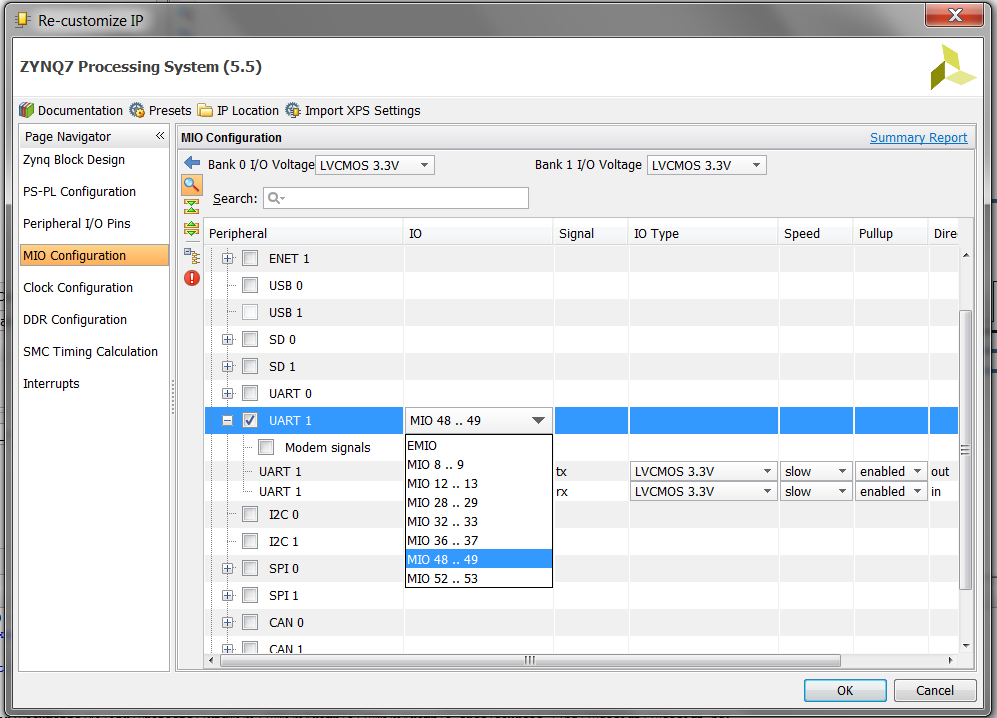
IO Configuration
It is important to understand the difference between the MIO and EMIO options seen in the IO column. The MIO (Multiplexed IO) pins are a fixed set of dedicated pins that certain peripheral functions can be assigned to. These are exported as part of the FIXED_IO port that Vivado made during the Block Automation earlier. MIO’s are only connected to the PS and not to the PL.
If a peripheral is routed through EMIO (Extended Multiplexed IO), Vivado will create a special port for that peripheral on the Zynq PS block that can be assigned like any other signal in the PL. EMIOs are simply wires from the PS to the PL.
For GPIO, MIOs are numbered 0-53. EMIOs are numbered 54-117. So if GPIO is routed through the EMIO, the numbering needs to be offset by 54 when writing software. GPIO[0] would be routed to IO 54, GPIO[1] to IO 55, and so on. This can be a bit confusing when all Vivado shows is a GPIO bus numbered [63:0].
Export Hardware
The hardware portion is almost ready, but there are a few finishing touches to make before exporting it to the SDK.
- First, right-click on the pwm0 port on the AXI Timer block.
- Click Make external . This exposes that signal to the top level so it can be directly connected to a pin.
- Connect the interrupt output of the AXI Timer to the IRQ_F2P input of the Zynq block.
- Next, right-click on the block design file in the Sources pane and select Create HDL Wrapper then Let Vivado manage wrapper and auto-update. This creates the top-level HDL file for the design.


- Then select Open Elaborated Design from the left and choose the IO Planning layout from the top.
- Change the I/O Standard for the pwm0 signal to LVCMOS33 .
- Set the package pin to H12 which corresponds to GPIO4 on the ZynqBerry / Raspberry Pi header. To see the full pin mapping for the ZynqBerry header, see the TE Master Pinout document linked in the Vendor Resources above. The DDR and FIXED_IO interfaces are assigned automatically.

The block diagram design should now be finished.
- On the left side of the window in the Flow Navigator, select Run Synthesis . Select Yes if it asks to save the block design file.
- When synthesis is complete, select Run Implementation .
- When implementation is complete, select Generate Bitstream.
- Go to File > Export > Export Hardware and check Include bitstream . Leave the location default which is the current project directory. Everything on the hardware side is now finished and software development can begin.
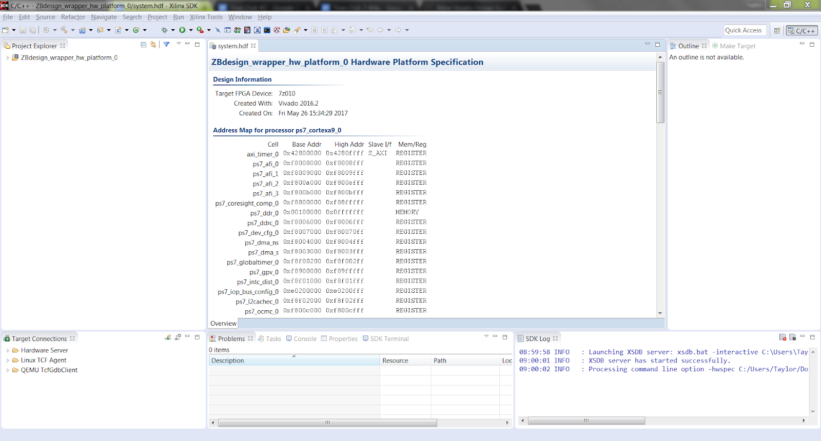
- Go to File > Launch SDK leaving the directories as .
Standalone Software Design
At the end of the previous step, the Xilinx SDK should have opened and imported the hardware that was just created. If it was successful, the address map for the available peripherals will be seen on the first screen. This section will provide a brief guide on setting up a bare-metal C project for the Zynq.
-
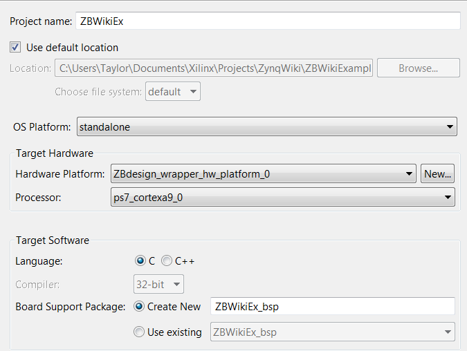
Go to File > New > Application Project . Set up the project with the settings below noting that the OS platform is set to standalone .
-
Click Next and confirm that the Hello World template is selected. Click Finis h to create the project.
Run Configuration
Before writing any application code, it is useful to set up run configurations for the project.
-
From the menu bar select Run > Run Configurations . In the left panel right-click Xilinx C/C++ application (GDB) and choose New . I set up two separate configurations, one for resetting the processor and loading new C code and one that does a full system reset and also reprograms the FPGA.
-
For the processor reset, go to the Application tab and select Browse … next to Project Name . Verify it is the name of the project that was just created. Select it and it will populate the Application field with that project’s .elf file.
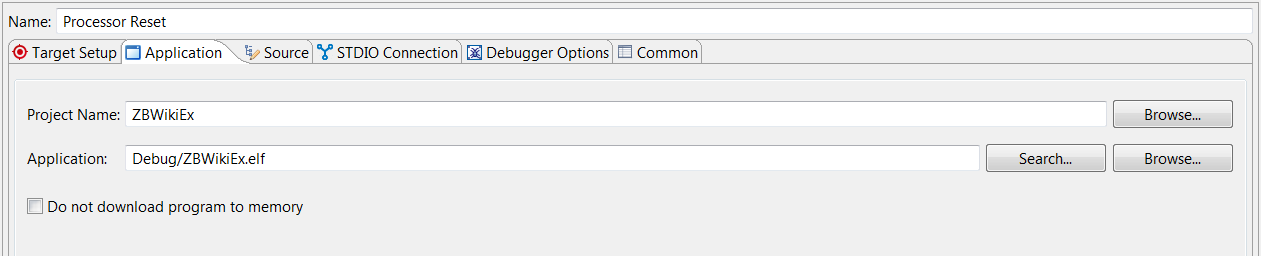
- Go back to the Target Setup tab and make sure that Reset Processor is selected in the dropdown menu at the bottom.

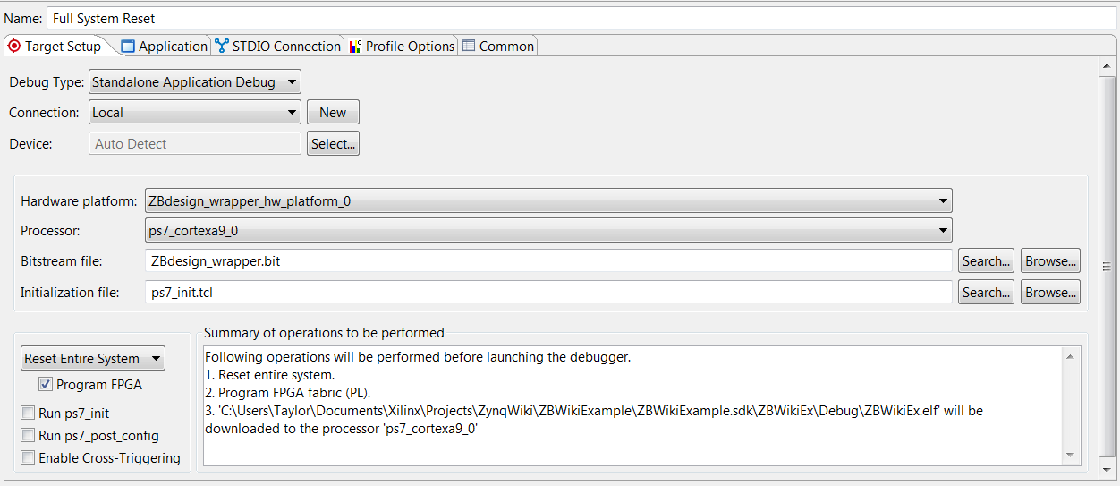
- (Optional) Follow the same steps to create a full system reset configuration, but modify the following items on the Target Setup tab:
- Select Search… next to the Bitstream file field. It should automatically find the bitstream generated in Vivado. Double-click it to populate the field.
- (Optional) Repeat step 1 to populate the Initialization file field with ps7_init.tcl.
- Select Reset Entire System from the dropdown and check the Program FPGA box.
Application Code
Expand the project directory in the left place and expand the source folder. Replace the contents of the generated helloworld.c with the code provided below.
Application Code Expand source
#include <stdio.h>
#include "platform.h"
#include "xil_printf.h"
#include "xtmrctr.h"
#include "xscugic.h"
#include "xil_exception.h"

// Timer variables
#define TMR_INTR_ID 	XPAR_FABRIC_AXI_TIMER_0_INTERRUPT_INTR
#define PWM_CONFIG		((1<<9) | (1<<2) | (1<<1))
#define TMR0_RELOAD		20000
#define TMR1_RELOAD 	10000

int status;
u32 control_reg;
u32 pwm;
s8 step = 4;

// Structures
XTmrCtr Timer;
XTmrCtr_Config *TimerConPtr;
XScuGic Intc;
XScuGic_Config *IntcConPtr;

void Timer0Callback(void *Inst)
{
	// Set duty cycle
	pwm += step;
	if(pwm >= TMR0_RELOAD || pwm == 0)
	{
		step = -step;
	}

	// Load duty cycle into Timer 1
	XTmrCtr_SetResetValue(&Timer, 1, pwm);

	// Clear interrupt flag (bit 8 in the Control & Status reg)
	control_reg = XTmrCtr_GetControlStatusReg(TimerConPtr->BaseAddress, 0) | (1<<8);
	XTmrCtr_SetControlStatusReg(TimerConPtr->BaseAddress, 0, control_reg);
}
void TimerSetup(void)
{
	// Initialize timer
	TimerConPtr = XTmrCtr_LookupConfig(XPAR_AXI_TIMER_0_DEVICE_ID);
	XTmrCtr_CfgInitialize(&Timer, TimerConPtr, TimerConPtr->BaseAddress);

	// Configure timers for PWM usage
	control_reg = XTmrCtr_GetControlStatusReg(TimerConPtr->BaseAddress, 0) | PWM_CONFIG;
	XTmrCtr_SetControlStatusReg(TimerConPtr->BaseAddress, 0, control_reg);
	control_reg = XTmrCtr_GetControlStatusReg(TimerConPtr->BaseAddress, 1) | PWM_CONFIG;
	XTmrCtr_SetControlStatusReg(TimerConPtr->BaseAddress, 1, control_reg);

	// Set starting values for timers
	XTmrCtr_SetResetValue(&Timer, 0, TMR0_RELOAD);
	XTmrCtr_SetResetValue(&Timer, 1, TMR1_RELOAD);

	// Assign function Timer0Callback to be called when interrupt occurs
	XTmrCtr_SetHandler(&Timer, (XTmrCtr_Handler)Timer0Callback, &Timer);

	// Enable interrupts for Timer 0 only
	XTmrCtr_EnableIntr(TimerConPtr->BaseAddress, 0);
}
int IntcSetup(void)
{
	// Enable exceptions in the ARM
	Xil_ExceptionEnable();

	// Configure Interrupt Controller
	IntcConPtr = XScuGic_LookupConfig(XPAR_PS7_SCUGIC_0_DEVICE_ID);
	status = XScuGic_CfgInitialize(&Intc, IntcConPtr, IntcConPtr->CpuBaseAddress);
	if(status != XST_SUCCESS)
	{
		return XST_FAILURE;
	}

	// Connect to hardware
	Xil_ExceptionRegisterHandler(XIL_EXCEPTION_ID_INT, (Xil_ExceptionHandler) XScuGic_InterruptHandler, &Intc);
	XScuGic_Connect(&Intc, TMR_INTR_ID, (Xil_ExceptionHandler) Timer0Callback, &Timer);
	XScuGic_Enable(&Intc, TMR_INTR_ID);
	return XST_SUCCESS;
}
int main()
{
    init_platform();
    TimerSetup();
    IntcSetup();
	print("Hello World!\n\r");
	XTmrCtr_Start(&Timer, 0);
	XTmrCtr_Start(&Timer, 1);
	print("Timers started.\n\r");
	while(1);
    cleanup_platform();
    return 0;
}
The first function Timer0Callback() is what creates the breathing effect, by incrementing or decrementing the duty cycle every time Timer 0 overflows. TimerSetup() sets the required register values to operate the timer in PWM mode and specifies Timer0Callback() as the function to be called when an interrupt occurs. Finally, IntcSetup() connects the interrupt from the timer to generic interrupt controller in the PS which is then connected to the ARM’s exception handler.
Xilinx’s API documentation and examples can be quickly accessed from the system.mss file that opens when a project is created. Most of the AXI peripherals that can be used follow a very similar API.

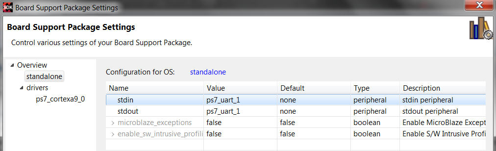
Modifying BSP Settings
Stdin and stdout will default to UART 0 if both of the UARTs are enabled. Since UART 0 is not connected to the USB to Serial adapter, this setting needs to be changed to UART 1.
Running the Application
- Open a terminal of your choice with 115200 baud and find the COM port that is created by the ZynqBerry.
- Connect an LED, through a suitable resistor, to GPIO4 (pin 7 on the header).
- Once the application code is ready to test, plug in the ZynqBerry and go back to Run > Run Configurations and choose the configuration that performs a full system reset and programs the FPGA with the bitstream created earlier. The code above will then be written into RAM and run.
Note : If errors occur during programming or the program doesn’t seem to be running it may be because the processor wasn’t initialized. Try checking the Run ps7_init and Run ps7_post_config options in the run configurations and running the program again.
The LED should be blinking with a breathing effect and a “Hello World” message will be visible in the terminal window.
Linux
A Linux image on the Zynq platform consists of the following components:
- First Stage Bootloader (FSBL)
- U-Boot
- Boot Image
- Device Tree
- Kernel Image
- Root Filesystem
The Xilinx Wiki has a great guide on how to build each of these components for a custom Linux system. This guide will demonstrate a method of creating a custom Linux image using the Xilinx PetaLinux SDK. The following example will use the Xilinx Linux kernel and a Debian/Ubuntu root file system, but will point how to modify the components.
There are certain requirements that a hardware system must meet in order to boot Linux. A full description can be found in Xilinx’s PetaLinux Reference Guide (UG1144). To summarize, the requirements for Linux are:
- One TTC (Triple Timer Counter)
- External memory controller with at least 32MB of memory
- One UART
- (Optional) Non-volatile memory such as QSPI Flash, SD/MMC
- (Optional) Ethernet
(Optional) Building a Custom Linux System with PetaLinux
Much of this section will follow the steps outlined in the Xilinx PetaLinux Reference Guide (UG1144). This section can be skipped if the pre-built files are being used.
-
Install PetaLinux following the instructions in the Reference Guide on a Linux machine. There are a number of dependencies that need to be installed first. Only a few Linux distributions are actually officially supported. However, it is possible for the tools to work on unsupported distributions, but results may vary. This example was done using Linux Mint 18.
-
Create a working directory using the command.
source <path-to-PetaLinux-install-directory>/settings.sh
- Create a new PetaLinux project.
petalinux-create --type project --template zynq --name ZynqBerryOS
# Move to new project directory
cd ZynqBerryOS
- Import .hdf file from Vivado. This command will open a menu for configuring Linux system options.
petalinux-config --get-hw-description=<path-to-hdf-file>
# To modify any settings later, simply use
# petalinux-config

- In the menu, configure the system according the application. The changes being made allow the use of a kernel source other than the one maintained by Xilinx, in this case the mainline kernel. Using the Xilinx kernel has the advantages of pre-made drivers for the Zynq platform for configuring the PL and certain AXI peripherals. The location of the device tree is also changed so that it resides on the SD card. Finally, the root filesystem is designated to be on the second partition of the SD card.
- Note : Depending on the kernel, the mounting location of the rootfs may change. So if /dev/mmcblk0p2 doesn’t work, try /dev/mmcblk1p2 .
- Going through each menu:
- Linux Components Selection
- Here you can direct PetaLinux to different sources for U-Boot, the Linux kernel, and package feeds for the rootfs.
- Keep the default settings here. The rootfs will be added independently of the selections here.
- (Optional) To use a different kernel source (also works for U-boot):
- Change kernel to remote .
- Under Remote linux-kernel settings set the git URL to the mainline kernel (or another preferred source): GitHub - torvalds/linux: Linux kernel source tree
- Auto Config Settings
- Keep defaults.
- Subsystem AUTO Hardware Settings
- SD/SDIO Settings
- Change Primary SD/SDIO to ps7_sd_1 .
- Advanced bootable images storage Settings
- dtb image settings
- Set Image Storage Media to primary sd .
- dtb image settings
- Keep the rest of the default settings.
- SD/SDIO Settings
- Kernel Bootargs
- Set according to preference. Example keeps the defaults and sets them in U-Boot.
- u-boot Configuration
- Keep defaults.
- Image Packaging Configuration
- Change Root filesystem type to SD card
- Verify Device node of SD device is set to /dev/mmcblk0p2
- Uncheck Copy final images to tftpboot
- Keep defaults.
- Firmware Version Configuration
- Keep defaults.
- Linux Components Selection
- Modify kernel settings to include the USB-Ethernet Bridge used on the board
petalinux-config -c kernel
-
In the kernel config menus
- Device drivers
- Network device support
- USB Network adapters
- Include Multi-purpose USB Networking Framework
- Include SMSC LAN95XX based USB2.0 10/100 ethernet devices
- Include Multi-purpose USB Networking Framework
- USB Network adapters
- Network device support
- Enable or modularize any additional modules required .
- Device drivers
-
Add the following lines to the device tree located in /subsystems/linux/configs/device-tree/system-top.dts.
/{
    usb_phy0: usb_phy@0 {
        compatible = "ulpi-phy";
        #phy-cells = <0>;
        reg = <0xe0002000 0x1000>;
        view-port = <0x0170>;
        drv-vbus;
    };
};

&usb0 {
    usb-phy = <&usb_phy0>;
} ;
- Build the image.
petalinux-build
- Package boot image containing the FSBL, FPGA bitstream, and U-Boot.
# Generate BOOT.bin file
petalinux-package --boot --fsbl ./images/linux/zynq_fsbl.elf --fpga <path-to-bit-file>.bit --u-boot

# Package everything to a prebuilt folder for convenience
petalinux-package --prebuilt --fpga <path-to-bit-file>.bit
Program Flash
The first step in preparing the system is to program the flash with the boot image (BOOT.bin). The boot image contains at least the FSBL and U-boot binaries, but may also contain the FPGA bitstream, kernel image, device tree, and rootfs depending on how the system is configured. In this example, it only contains the FSBL, U-Boot, and FPGA bitstream.
- To program BOOT.bin into flash, open the SDK with any workspace and select Xilinx Tools > Program Flash . Browse for the BOOT.bin file in the PetaLinux prebuilt folder. Select Program to write the file into flash.
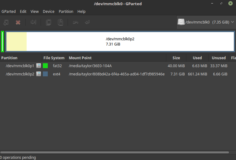
Prepare SD Card
- Format an SD card with two partitions: one FAT32 for the boot section and one EXT4 for the root filesystem. Use a method of your choice like parted, dd, etc. Assuming the SD card is /dev/mmcblk0.
sudo parted /dev/mmcblk0

# Check existing partitions
print

# Remove any existing partitions if any
rm 1
rm 2

# Create a boot partition, optimally aligned
-a optimal mkpart primary fat32 0 40MiB

# Create the rootfs partition with the rest of the card
-a optimal mkpart primary ext4 40MiB 100%

# Disable lba flag on partition 2
set 2 lba off

# Check new partitions
print

# Result should look something like this:

#Number  Start   End     Size    Type     File system  Flags
# 1      1049kB  39.8MB  38.8MB  primary  fat32        lba
# 2      41.9MB  7901MB  7859MB  primary  ext4
- Mount the SD card.
sudo mkdir /media/boot
sudo mkdir /media/rootfs

sudo mount /dev/mmcblk0p1 /media/boot
sudo mount /dev/mmcblk0p2 /media/rootfs
- Copy the kernel image, image.ub, and the device tree, system.dtb, onto the first partition of the SD card.
sudo cp <prebuilt directory>/linux/images/image.ub /media/boot
sudo cp <prebuilt directory>/linux/images/system.dtb /media/boot
- Download and extract a root file system to the second SD card partition. For this example, use the Debian or Ubuntu rootfs from the ZC702 example.
Debian 9
 # Download Debian release
wget -c https://rcn-ee.com/rootfs/eewiki/minfs/debian-9.0-minimal-armhf-2017-06-18.tar.xz

# Extract
tar xf debian-9.0-minimal-armhf-2017-06-18.tar.xz

# Copy to SD card
sudo tar xfvp ./*-*-*-armhf-*/armhf-rootfs-*.tar -C /media/rootfs/
sync
sudo chown root:root /media/rootfs/
sudo chmod 755 /media/rootfs/
Ubuntu 16.04 LTS
# Download Ubuntu release
wget -c https://rcn-ee.com/rootfs/eewiki/minfs/ubuntu-16.04.2-minimal-armhf-2017-06-18.tar.xz

# Extract
tar xf ubuntu-16.04.2-minimal-armhf-2017-06-18.tar.xz

# Copy to SD card
sudo tar xfvp ./*-*-*-armhf-*/armhf-rootfs-*.tar -C /media/rootfs/
sync
sudo chown root:root /media/rootfs/
sudo chmod 755 /media/rootfs/
- Copy kernel modules from the PetaLinux build.
sudo rsync -vrL --ignore-existing <path-to-Petalinux-project>/build/linux/rootfs/targetroot/lib/modules/ /media/rootfs/lib/modules/
- Add file systems table
sudo sh -c "echo '/dev/mmcblk0p2  /  auto  errors=remount-ro  0  1' >> /media/rootfs/etc/fstab"
sudo sh -c "echo '/dev/mmcblk0p1  /boot/uboot  auto  defaults  0  2' >> /media/rootfs/etc/fstab"
- Unmount SD card
sudo umount /media/boot
sudo umount /media/rootfs
- Install the SD card in the ZynqBerry.
- Connect the ZynqBerry to a PC with a USB cable and open a terminal to the corresponding COM port at 115200 baud.
- In U-Boot, make the following changes before booting.
setenv cp_dtb2ram 'fatload mmc 1 ${dtbnetstart} ${dtb_img}'
setenv cp_kernel2ram 'fatload mmc 1 ${netstart} ${kernel_img}'
setenv default_bootcmd 'run cp_kernel2ram && run cp_dtb2ram && bootm ${netstart} - ${dtbnetstart}'
setenv bootargs 'console=ttyPS1,115200 earlyprintk root=/dev/mmcblk0p2 rw rootwait'
saveenv
boot
- Log in using the appropriate username/password combination
| Distribution | Username | Password |
|---|---|---|
| Debian 9 | debian | temppwd |
| Ubuntu 16.04 LTS | ubuntu | temppwd |
Software Design
The software design flow for the ZynqBerry works just like any other embedded Linux platform. Typically, this will involve making a kernel module that makes the memory locations of any peripherals accessible from user space. Below is some sample code for a kernel module that implements the bare-metal program shown above.
axitimer.c
#include <linux/module.h>
#include <linux/kernel.h>
#include <linux/init.h>
#include <linux/interrupt.h>
#include <linux/irq.h>
#include <linux/platform_device.h>
#include <linux/slab.h>
#include <linux/delay.h>
#include <asm/io.h>


#define DEVICE_NAME "axitimer"

/* Address definitions */
#define AXI_TIMER_BASE_ADDR 0x42800000
#define AXI_TIMER_HIGH_ADDR 0x4280FFFF

#define AXI_TIMER_TCSR0_OFFSET  0x00
#define AXI_TIMER_TLR0_OFFSET   0x04
#define AXI_TIMER_TCR0_OFFSET   0x08
#define AXI_TIMER_TCSR1_OFFSET  0x10
#define AXI_TIMER_TLR1_OFFSET   0x14
#define AXI_TIMER_TCR1_OFFSET   0x18

/* Bit masks for CSR registers */
#define AXI_TIMER_CSR_CASC          (1 << 11)
#define AXI_TIMER_CSR_ENALL         (1 << 10)
#define AXI_TIMER_CSR_PWMA          (1 << 9)
#define AXI_TIMER_CSR_TINT          (1 << 8)
#define AXI_TIMER_CSR_ENT           (1 << 7)
#define AXI_TIMER_CSR_ENIT          (1 << 6)
#define AXI_TIMER_CSR_LOAD          (1 << 5)
#define AXI_TIMER_CSR_ARHT          (1 << 4)
#define AXI_TIMER_CSR_CAPT          (1 << 3)
#define AXI_TIMER_CSR_GENT          (1 << 2)
#define AXI_TIMER_CSR_UDT           (1 << 1)
#define AXI_TIMER_CSR_MDT           (1 << 0)

#define PWM_CONFIG                          (AXI_TIMER_CSR_PWMA | AXI_TIMER_CSR_GENT | AXI_TIMER_CSR_UDT)
#define TMR0_RELOAD                         20000
#define TMR1_RELOAD                         10000

void *timer_virt_addr;
static struct platform_device *pdev;

int timer_irq;

uint32_t pwm = 0;
int8_t step = 4;

static irqreturn_t axitimer_isr(int irq, void *dev_id)
{
    uint32_t reg0;

    /* Set duty cycle */
    pwm += step;
    if(pwm >= TMR0_RELOAD || pwm == 0)
    {
        step = -step;
    }

    /* Load new value into timer1 */
    iowrite32(pwm, timer_virt_addr + AXI_TIMER_TLR1_OFFSET);

    /* Clear interrupt flag */
    reg0 = ioread32(timer_virt_addr + AXI_TIMER_TCSR0_OFFSET) | AXI_TIMER_CSR_TINT;
    iowrite32(reg0, timer_virt_addr + AXI_TIMER_TCSR0_OFFSET);

    return IRQ_HANDLED;
}

static int __init axitimer_init(void)
{
    uint32_t temp0;
    uint8_t count = 0;
    unsigned long mask;

    printk(KERN_INFO "Initializing AXI Timer module...\n");

    timer_virt_addr = ioremap_nocache(AXI_TIMER_BASE_ADDR, AXI_TIMER_HIGH_ADDR - AXI_TIMER_BASE_ADDR + 1);

    /* Configure timers for PWM usage */
    iowrite32(PWM_CONFIG | AXI_TIMER_CSR_ENIT, timer_virt_addr + AXI_TIMER_TCSR0_OFFSET);       // Also enable interrupts for timer 0 only
    iowrite32(PWM_CONFIG, timer_virt_addr + AXI_TIMER_TCSR1_OFFSET);

    /* Set starting values */
    iowrite32(TMR0_RELOAD, timer_virt_addr + AXI_TIMER_TLR0_OFFSET);
    iowrite32(TMR1_RELOAD, timer_virt_addr + AXI_TIMER_TLR1_OFFSET);

    // Set up and try to probe for interrupts
    do
    {
        mask = probe_irq_on();

        /* Turn on timer 0 to generate an interrupt */
        temp0 = ioread32(timer_virt_addr + AXI_TIMER_TCSR0_OFFSET) | AXI_TIMER_CSR_ENT;
        iowrite32(temp0, timer_virt_addr + AXI_TIMER_TCSR0_OFFSET);

        mdelay(1);      // Delay and hopefully get an interrupt

        /* Turn off timer */
        temp0 = ioread32(timer_virt_addr + AXI_TIMER_TCSR0_OFFSET) & ~(AXI_TIMER_CSR_ENT);
        iowrite32(temp0, timer_virt_addr + AXI_TIMER_TCSR0_OFFSET);

        timer_irq = probe_irq_off(mask);

        if(timer_irq == 0)
        {
            printk(KERN_INFO "axitimer_init: No IRQ reported by probe.\n");
        }

    } while(timer_irq < 0 && count++ < 5);

    if(timer_irq == 0)
    {
        printk(KERN_ERR "axitimer_init: IRQ probe failed.\n");
        return -EIO;
    }

    /* Request IRQ */
    if(request_irq(timer_irq, axitimer_isr, 0, DEVICE_NAME, NULL))
    {
        printk(KERN_ERR "axitimer_init: Cannot register IRQ %d\n", timer_irq);
        return -EIO;
    }

    /* Register device */
    pdev = platform_device_register_simple(DEVICE_NAME, 0, NULL, 0);
    if(pdev == NULL)
    {
        printk(KERN_WARNING "axitimer_init: Adding platform device failed.\n");
        kfree(pdev);
        return -ENODEV;
    }

    /* Start timers */
    temp0 = ioread32(timer_virt_addr + AXI_TIMER_TCSR0_OFFSET) | AXI_TIMER_CSR_ENALL;       // Use ENALL to start both timers simultaneously
    iowrite32(temp0, timer_virt_addr + AXI_TIMER_TCSR0_OFFSET);

    printk(KERN_INFO "AXI Timer configured.\n");
    return 0;

}

static void __exit axitimer_exit(void)
{
    iounmap(timer_virt_addr);
    free_irq(timer_irq, NULL);
    // Unregister device
    platform_device_unregister(pdev);
    printk(KERN_INFO "AXI Timer module removed.\n");
}

module_init(axitimer_init);
module_exit(axitimer_exit);

MODULE_AUTHOR("TR");
MODULE_DESCRIPTION("Example driver for Xilinx AXI Timer.");
MODULE_LICENSE("GPL");
To build and install the module:
sudo apt-get update
sudo apt-get install build-essential
cd <directory-containing-axitimer.c>
make CFLAGS_MODULE=-fno-pic -C /lib/modules/$(uname -r)/build M=$(pwd) modules

sudo /sbin/insmod axitimer.ko
The LED on GPIO4 should now be on and “breathing.”
Conclusion
The goal of this guide is to provide a basic outline of setting up a project for the ZynqBerry from scratch both with and without Linux. Much of the guide is also generic to any Zynq-based platform and can be translated to other target boards. To purchase the ZynqBerry or other single board computers, visit us at DigiKey.
Contact
Any questions, comments, or feedback can be sent to eewiki@digikey.com.