Created by Colton Parks, last modified by BenH on [Sep 01, 2016]
Introduction:
This article is meant to help beginners understand how a stepper motor works and how to drive a stepper. Controlling stepper motors is a broad topic, and this article is meant to get you started. There are two types of steppers: bipolar and unipolar.
Bipolar Motors:

A bipolar stepper motor has four wires and two coils. To make it rotate, you need to send current through the coils. Each wire needs to be capable of being driven high and low. Here is how to drive the current to make the stepper rotate.

To understand why this works, consider a simple stepper that only has four steps. In the first stage, it will align the magnet with the first coil. The next step will rotate the magnet 90 degrees. Sending current backwards through the first coil reverses the magnetic polarity. Opposite coils are connected, but generate opposing magnetic fields relative to the central magnet.

Of course, most stepper motors have more than 4 steps. Your standard stepper motor will have 200 steps per revolution. Rotating the motor this way is called full-stepping. Half-stepping is pretty simple once you have full-stepping working. You can send current through both coils at the same time, which will double your resolution.
Stepper motor drivers can also use microstepping, which modulates the current through the coils. A typical motor controller can implement 16 micro-steps per full step. Some chips take care of modulating current, but older chips need to be “tuned” for the stepper it drives. Microstepping further divides full steps up to 256 micro-steps, allowing a typical 200 step motor become a 51,200 step motor! Microstepping also reduces noise in the motor and makes it run smoother and more efficient.

Half-step between full-steps 1 and 2
How to control the current in a coil:
The most common setup to control the current through the windings is to use what’s called an H-bridge. It is a set of four transistors that can pull each wire high or low. You can also use MOSFETs in place of transistors, but the wiring will be a little different. This diagram shows how you can send current either direction through the H-bridge. You just need to turn on the transistors in the path.

You must make sure that no two transistors on the same side should be on at the same time. This will short your circuit by providing a low resistance path from power to ground. You should also be aware that the transistors may take some time to transition from on to off. It is not recommended to switch the current through the coil rapidly unless you know what you are doing.

This still isn’t the complete picture. A spinning motor will generate voltage. To save the transistors, it would be a good idea to place flyback diodes.

This will prevent the motor from generating a high voltage, which could destroy your transistors or even your driver. If your voltage driving the stepper motor is higher than the voltage your MCU outputs, you will need to add another transistor to control the PNP transistors.

When you turn on the extra NPN transistors, it will allow current to flow out of the base of the PNP transistor (pin 1), turning it on. All that’s needed now is current-limiting resistors on the base of all NPN transistors.
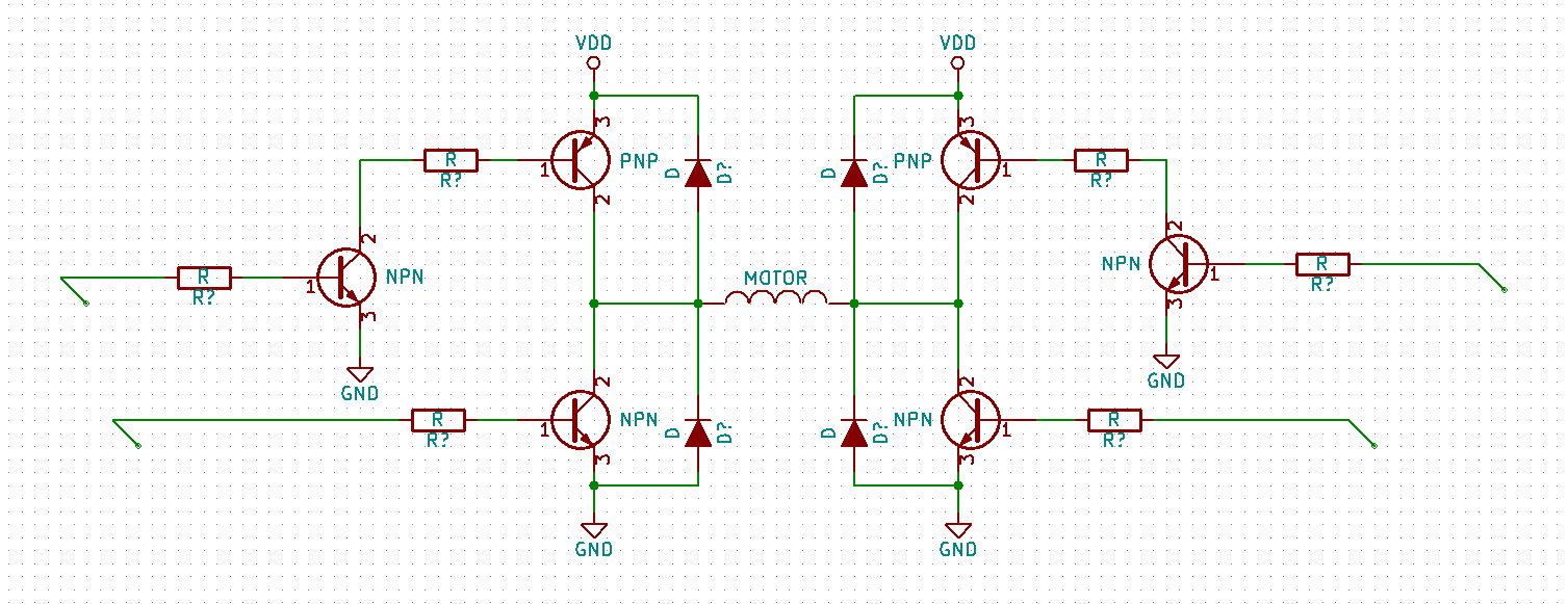
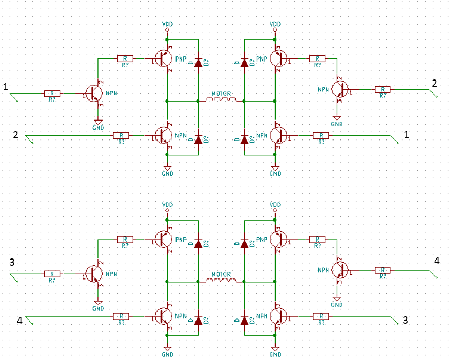
That’s it! This H-bridge will control the current through one of the windings. Since there are two windings, we need to double this circuit.

Now you can get a good count of the components you will need. Using a dual H-bridge isn’t the only way to drive stepper motors. You can also buy stepper motor drivers, which will have this dual H-bridge built in (although drivers usually use MOSFETS and other tricks). If you want to reduce the BOM count (and sometimes get more functionality), I would recommend looking at stepper motor drivers. You will need to look at the datasheet to see what the chip offers. Some chips just provide transistors and diodes, while others take total control of the current through the coils.
Microstepping:
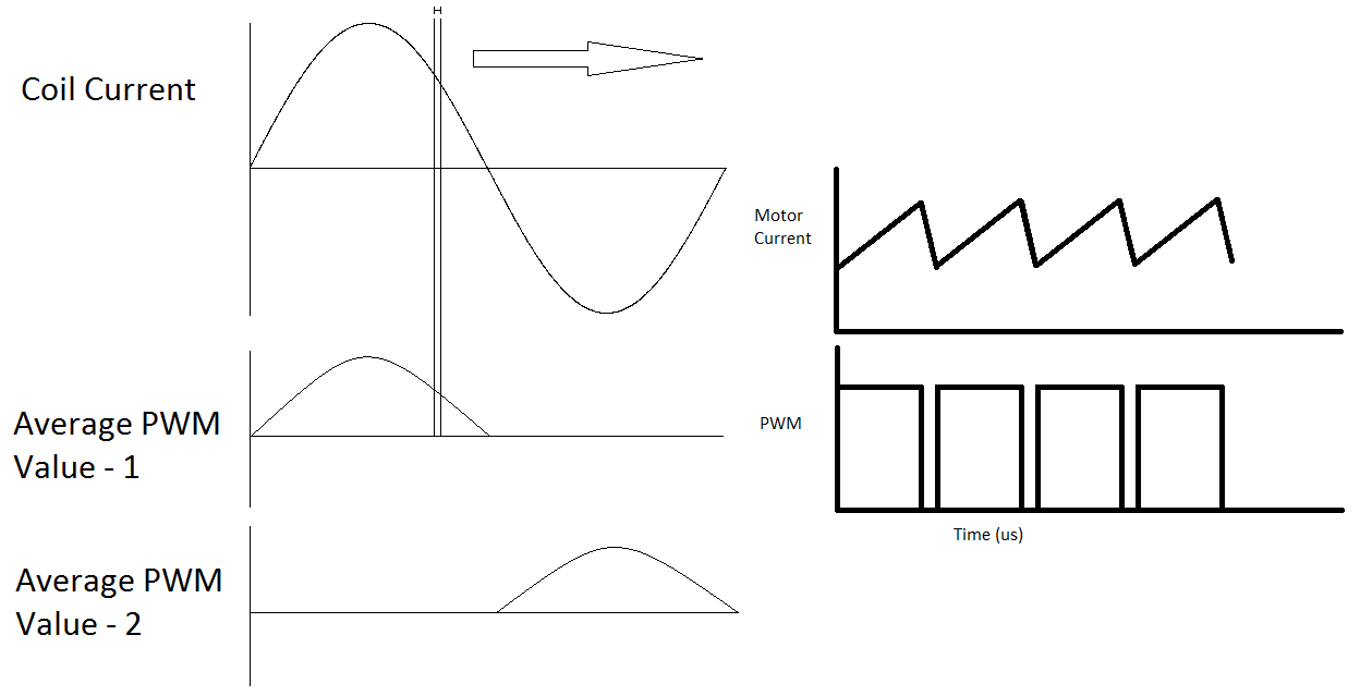
Microstepping involves sending a Pulse Width Modulating signal to the transistors. This is an easy way to control the current in the motor coil. The PWM values chosen beforehand are placed in a sine lookup table. Typically, a PWM frequency of 20-40 kHz is chosen. Anything below 20 kHz the human ear can hear. The frequency is kept lower than 40 kHz to increase efficiency and reduce power dissipation in the transistors. When the PWM signal is high, the current travels through the transistors. When the PWM signal is low, the current travels through the diodes. This is a very crude implementation of microstepping, but it gives the general idea of how it works. Motor drivers that use MOSFETS can control how fast the motor current decreases, or decays. The current waveform for drivers look more like this:

The fast decay periods and slow decay periods must be manually optimized for the motor it drives. Some new chips automatically adjust the decay periods based on the current it senses, but older chips might need to be optimized (or tuned).
Transistor Basics:
A transistor is a current-controlled current limiting device. There are three pins to a transistor: the base, collector, and emitter. (denoted by c, b, and e).
NPN Transistors:
NPN transistors have mostly been replaced by MOSFETS, but there are still some applications where a transistor might be more desirable. They aren’t as susceptible to Electro Static Discharge (ESD) and take less voltage to use. The largest disadvantages are that they can’t push as much current as a MOSFET and aren’t as efficient. Using a TIP120 supplied by 5mA, I can control a 60V load up to 5A (read the datasheet for specific operating characteristics).
This is a typical small signal NPN transistor. When a small current passes from the base to the emitter, a larger current is allowed to flow from the collector to the emitter. It is important to remember them as current-based devices.

A Darlington pair is a package of two transistors. The gain doubles as well as the forward voltage.

Any transistor can be thought of as a diode and a dependent current source.

The current through the dependent current source is β (beta) multiplied by the current through the diode (ib). β is called the gain of the transistor. This will have a pretty large variance from transistor to transistor, so don’t rely on this value to be true! This model only works if the transistor isn’t saturated. A transistor is called saturated if there is more than enough current going through the base such that the transistor isn’t limiting current through the collector-emitter anymore. (If you use the transistor as a switch, you should have the transistor either saturated or off to prevent heating and power loss.)
Diodes have a nominal voltage drop of 0.7V across the anode and cathode. So, the voltage drop from the base to the emitter is 0.7 volts (for a Darlington, this would be 1.4V).

The diode being an integral part of a transistor is why you should place NPN transistors to control ground and PNP transistors to control power. Consider two almost equivalent circuits.

In the first circuit, imagine you have enough current into the base from the 3.3V source to completely saturate the transistor (the transistor isn’t limiting any current from the load ![]() . There is a small voltage drop across the collector and emitter, but it is pretty minor. There is 11.8 volts across the load. The voltage across the current-limiting resistor is 2.6V. This is important when you calculate the size of the resistor.
. There is a small voltage drop across the collector and emitter, but it is pretty minor. There is 11.8 volts across the load. The voltage across the current-limiting resistor is 2.6V. This is important when you calculate the size of the resistor.
In the second circuit, the same resistor is used to theoretically limit the same current. But because a transistor acts like a diode between the base and emitter, the emitter MUST be 0.7 volts less than the base. 2.6 volts is the absolute most the emitter can be (it will probably be much less due to voltage division from the two resistors.) The transistor isn’t limiting current at this point, it is limiting voltage. Regardless, the transistor is dissipating the excess power as heat. The voltage across the load is only 2.6V.
PNP Transistors:
This is what a typical PNP transistor looks like in a schematic. It is similar to an NPN transistor, except that current must flow from the emitter to the base to allow current to flow from the emitter to collector. When a small current passes through the diode, a much larger current is allowed across the emitter and collector.

A transistor can be thought of as a diode and dependent current source. The current from the dependent current source is ![]() . Just like an NPN, a diode exists across the base to emitter. There will still be a 0.7V drop across the diode. It is just facing the other direction.
. Just like an NPN, a diode exists across the base to emitter. There will still be a 0.7V drop across the diode. It is just facing the other direction.

Here is how you might use it in a circuit. To turn it on, let pin 1 be 0.7V lower than pin 3. To shut off the transistor, pin 1 needs to be at the same voltage as VCC. This is important to keep in mind when controlling it with op amps. If the op amp doesn’t go rail to rail, it won’t shut off the PNP transistor entirely. It also makes it difficult to drive higher voltages. If you tried to control a 12v supply with 3.3v, you could never shut off the transistor. 3.3v is always less than 12v. This is why I usually pair them up with a small signal NPN. If the NPN is off, current can’t flow through the diode, and the PNP is off.

How to choose your discrete components:
Diodes : Choose diodes that are current rated for your application. When switching from on to off, the current in the motor must pass through the diodes. To avoid excessive heat, try to find diodes that have a lower forward voltage (. This is especially true if you plan to implement microstepping.
Transistors : Your H-bridge transistors must also be current rated for your application. You can try to avoid excessive heat by choosing a lower collector-emitter saturation voltage. A higher transition frequency can also be beneficial, as it will lower the amount of time the transistor is in the active state. The maximum power value denotes how much power the transistor can dissipate. A low power dissipation means the transistor is meant to be used as a switch.
Small signal transistors : These can be pretty unspectacular. The biggest attribute to look for is that the Collector-emitter breakdown voltage is higher than your motor power supply. A higher frequency transition is also good. Transition times will stack between the two transistors (giving an overall much lower transition frequency.)
Resistors : The resistors should be easy to choose. They will see a fraction of the current passing through the transistors. The two NPN resistors will also see minimal voltage levels. The resistor attached to the base of the PNP is the only one to look out for. Once you know the amount of current passing through the transistor, the voltage is essentially the motor supply voltage. Power ratings above ¼ watt should be more than enough for most applications.
Example scenario:
I will use an example situation to show how to calculate the values needed for resistors. This is the scenario:
Motor:
12V, 0.33A.

Power supply:

Microcontroller:
EFM32GG-STK3700. The logic levels for this board are 3.3v. Each pin is capable of supplying up to 20mA.
Transistors:
I happen to have some TIP120 and TIP125 transistors that I will use to drive the H-bridge. They are capable of driving 5A.


Yikes! Both transistors seem to have a collector-emitter saturation of 4V! Across both transistors, this would only give my motor 4V to run. We better look into that spec a little deeper.

The datasheet scared me for a second! Looks like the typical saturation voltage is under 1V with my application. In higher current situations, the saturation voltage increases to about 1.2V. A small signal NPN will usually have a saturation voltage of 0.2V. Why is a Darlington pair so much higher?

Consider point D. If the first transistor is saturated, D will be 0.2V less than C. Remember that the second transistor has a diode built in. E MUST be 0.7V less than D, otherwise current will not flow. Overall, E is 0.9V less than C. This would explain why the Darlington pair has a higher saturation voltage. When thinking about current flow in a circuit, it is best to rely on simple truths to avoid over complication.
Now we need resistors and diodes. I had some 1N4148 diodes on hand. They aren’t current rated for my application. However, I wasn’t planning on microstepping the motors.

If you look closer at the current capabilities, the datasheet says it can handle 300mA of forward current. Also, it can handle a surge of 1A for 1 second. The current in the motor shouldn’t be more than 1A for 1 second.

Calculating the resistors in an H-bridge:
Now that the part selection is mostly done, we can focus on the resistors. To start, you need to consider the current through the transistors.
Our load current is 0.33A. Therefore, ![]()
The power consumed by the PNP resistor is VI = 120.001 = 12mW. Virtually any size resistor will work. The smallest power rating Digi-key offers on surface mount resistors is 12.5mW.
The gain of my transistors near the operating region is close to 1000 at 25 degrees Celsius.

Therefore, I should supply 330 uA to the base of the transistors. To be on the safe side, I will supply 1mA (three times as much. Since I’m driving 330 mA, I don’t care about another 1 mA. Usually double the current is a safe bet.)
Now that we know the current needed, we can look at the voltages.
Since the PNP has a diode built in, the voltage at point B will be 1.4V less than VDD (12V), so Vb = 10.6V.
If the leftmost NPN is saturated, the collector-emitter voltage will be 0.2V. So, Va = 0.2V.
That means the voltage across the resistor is 10.4V. We need 1mA to travel through the resistor. Using V=I*R,
R = V/I = 10400. A 10k resistor will do fine. This value doesn’t need to be exact, since we already accounted for any gain tolerances when we tripled the current.

The next transistor will be the other Darlington pair. The collector current is 330mA. The gain is also around 1000 near my operating point. I should only need 330uA, but I will triple it to 1mA to make sure I account for any tolerances.
The voltage at point D is 1.4V. My MCU at C can supply 3.3V. The voltage across the resistor is 1.9V. Using V=I*R, R=V/I=1900. A 2k2 resistor or a 1k8 resistor will work.

The last resistor to compute is the one controlling the PNP transistor. The collector current is 1mA. A typical small signal transistor will have a gain of 100. It can also be lower at lower currents. Double check the datasheet for your transistor. The current needed to power this transistor is only 10uA. To be on the safe side, I will calculate for 100uA. The voltage at F is 0.7V. The voltage at E is again 3.3V. The voltage across the resistor is 2.6V. Using R=V/I, R=26k. Anything from 20k to 50k will work. I used 28k resistors.

That’s how you setup an H-bridge! To control it, you need to power the wires:
WARNING: either don’t connect the motor supply voltage to VM or don’t turn on the voltage supply until everything is connected. When reconnecting pins and moving wires, be SURE that the high voltage power supply is off. You can very easily blow out all of your ICs. Don’t say I didn’t warn you.
Spin the motor by turning on only pin 1, then 3, then 2, then 4. Or, go in the reverse order (4,2,3,1). To ensure that a power to ground occurrence doesn’t happen, turn off all pins when switching states.
Example code for an H-bridge:
Example code using full steps:
/**************************************************************************//**
 * @file
 * @brief Empty Project
 * @author Energy Micro AS
 * @version 3.20.2
 * @section License
 * <b>(C) Copyright 2014 Silicon Labs, http://www.silabs.com</b>
 *******************************************************************************
 *
 * This file is licensed under the Silicon Labs Software License Agreement. See
 * "http://developer.silabs.com/legal/version/v11/Silicon_Labs_Software_License_Agreement.txt"
 * for details. Before using this software for any purpose, you must agree to the
 * terms of that agreement.
 *
 ******************************************************************************/
#include "em_device.h"
#include "em_chip.h"
#include "em_cmu.h"
#include "em_system.h"
#include "em_gpio.h"
volatile uint32_t msTicks;
#define TOTAL_STEPS      4
uint32_t STEPS[TOTAL_STEPS] = {0b1000, 0b0010, 0b0100, 0b0001};             //1,3,2,4
uint16_t STEP = 0;
/* ************* Systick Handler ***************** */
void SysTick_Handler(void) {
    msTicks++;
}
/* ************* Delay function ****************** */
void Delay(uint32_t dlyTicks) {
    uint32_t curTicks = msTicks;
    while((msTicks - curTicks) < dlyTicks);
}
/* ************* Output to H-bridge ************** */
void setStep(void) {
      GPIO->P[3].DOUTCLR = 0xF;                  //Shut off all pins.
      GPIO->P[3].DOUTSET = STEPS[STEP];          //Output the steps
}
/* ************* Main function ******************* */
int main(void)
{
    CHIP_Init();
    CMU->HFRCOCTRL = 0x30; // Set RC clock to 1 MHz
    CMU->HFPERCLKEN0 =(1<<13); //Enable GPIO clock

    if (SysTick_Config(CMU_ClockFreqGet(cmuClock_CORE) / 1000)) while (1) ;         //Setup SysTick

/* ****************** Setup pushbuttons and H-bridge outputs ****************** */
    GPIO->P[1].MODEH = 0x110;                //Setup RB9 and RB10 as input
    GPIO->P[3].MODEL = 0x5555;               //Setup PD0-PD3 as push pull output. These go directly to the H-bridge
    GPIO->P[3].CTRL = 2;                     //High drivemode
    GPIO->P[3].DOUT = 0x0000;                //They should already be all low.
                                            //H-bridge pins 1,2,3,4 map to pins 3,2,1,0 on port D.
  /* Infinite loop */
  while (1) {
      if(!GPIO_PinInGet(gpioPortB,9)) {                         //If button 0 is pressed
          STEP = (STEP + 1) % TOTAL_STEPS;                      //Increment the step
          setStep();                                            //Output to the H-bridge
      }
      else if(!GPIO_PinInGet(gpioPortB, 10)) {                  //If button 1 is pressed.
          STEP = (STEP + TOTAL_STEPS-1) % TOTAL_STEPS;          //Decrement the step
          setStep();                                            //Output to the H-bridge
      }
      Delay(10);                                                //Short delay to let motor rotate
  }
}
Example code using half steps:
/**************************************************************************//**
     * @file
 * @brief Empty Project
     * @author Energy Micro AS
 * @version 3.20.2
 ******************************************************************************
 * @section License
 * <b>(C) Copyright 2014 Silicon Labs, http://www.silabs.com</b>
 *******************************************************************************
 *
 * This file is licensed under the Silicon Labs Software License Agreement. See
 * "http://developer.silabs.com/legal/version/v11/Silicon_Labs_Software_License_Agreement.txt"
 * for details. Before using this software for any purpose, you must agree to the
 * terms of that agreement.
 *
 ******************************************************************************/
#include "em_device.h"
#include "em_chip.h"
#include "em_cmu.h"
#include "em_system.h"
#include "em_gpio.h"
volatile uint32_t msTicks;
#define TOTAL_STEPS      8
uint32_t STEPS[TOTAL_STEPS] = {0b1000, 0b1010, 0b0010, 0b0110, 0b0100, 0b0101, 0b0001, 0b1001};
//1, 1and3, 3, 3and2, 2, 2and4, 4, 4and1

/* ************* Systick Handler ***************** */
void SysTick_Handler(void) {
    msTicks++;
}
/* ************* Delay function ****************** */
void Delay(uint32_t dlyTicks) {
    uint32_t curTicks = msTicks;
    while((msTicks - curTicks) < dlyTicks);
}
/* ************* Output to H-bridge ************** */
void setStep(uint32_t STEP) {
      GPIO->P[3].DOUTCLR = 0xF;                                  //Shut off all pins.
      GPIO->P[3].DOUTSET = STEPS[(STEP % TOTAL_STEPS)];          //Output the steps
}
/* ************* Main function ******************* */
int main(void)
{
    CHIP_Init();
    CMU->HFRCOCTRL = 0x30; // Set RC clock to 1 MHz
    CMU->HFPERCLKEN0 =(1<<13); //Enable GPIO clock

    if (SysTick_Config(CMU_ClockFreqGet(cmuClock_CORE) / 1000)) while (1) ;         //Setup millisecond tick counter

    /* ****************** Setup pushbuttons and H-bridge outputs ****************** */
    GPIO->P[1].MODEH = 0x110;                //Setup RB9 and RB10 as input
    GPIO->P[3].MODEL = 0x5555;               //Setup PD0-PD3 as push pull output. These go directly to the H-bridge
    GPIO->P[3].CTRL = 2;                     //High drivemode
    GPIO->P[3].DOUT = 0x0000;                //They should already be all low.
                                            //H-bridge pins 1,2,3,4 map to pins 3,2,1,0 on port D.
int32_t STEP = 0;

  /* Infinite loop */
  while (1) {
      if(!GPIO_PinInGet(gpioPortB,9)) {                         //If button 0 is pressed
          STEP += 1;                                            //Increment the step
          setStep(STEP);                                        //Output to the H-bridge
      }
      else if(!GPIO_PinInGet(gpioPortB, 10)) {                  //If button 1 is pressed.
          STEP -= 1;                                            //Decrement the step
          setStep(STEP);                                        //Output to the H-bridge
      }
      Delay(10);                                                //Short delay to let motor rotate
  }
}
Alternatives to using discrete components:
First, you must decide what level of control you will leave to the chip. Stepper drivers can be as simple as an H-bridge package. The product train gets incrementally more complex, and you can choose exactly where to step off. Texas Instruments provide a wide array of drivers with varying degrees of control. For any stepper motor application, Texas Instruments will have a chip for it. Allegro also has a wide variety of drivers. The drivers that have the most functionality built in are the Trinamic chips.
STMicroelectronics L293D – Quad half bridge, capable of driving 600mA per channel. This would be a substitute of the above schematic. You still need to control which pins to drive high and low. Boards like the Arduino motor shield will use this kind of chip. $3.90
TMC SILENTSTEPSTICK – Stepper motor driver controlled by step and direction. Trinamic offers tons of functionality in a tiny, affordable package. This chip is capable of 256 micro-step interpolation with current sensing (no tuning necessary). This is the evaluation board for the TMC2100. It will drive up to 1.2A. $7.27
TMC5130-EVAL-KIT – Stepper motor driver controlled by SPI/one-wire UART or step and direction. This chip is the Rolls Royce of stepper motor drivers. The evaluation kit is useful for determining what settings work best for your motor. Beware of the high voltage VM line. $143.02
The chip itself is the TMC5130 at $6.39
The Silent Step Stick :
This is a breakout for the TMC2100. It was designed by Watterott to be used in 3D printing. It has two 0.11 ohm sense resistors, giving it a maximum RMS current of 1.74A. The potentiometer allows you to control the current from 0 to 1.7A.

Purchase link – Digi-key’s website
Datasheet – Contains information useful for the TMC2100
Board information – Includes the schematic and board layout.
Github Trinamic chip data – Look for v11. This contains everything necessary to understand the chip.
Solder the headers:
Solder the headers to the board. If you want to make use of the Configuration input pin 3, solder that gap first (99% of you don’t need to worry about it). If you plan on breadboarding or using a socket, be sure to keep the bottom side up (It is labeled TOP). This will allow easier access to the potentiometer. If you plan on running substantial motor current (greater than half an amp), add a small heatsink with thermally conductive double-sided tape to the exposed vias. The vias on the top of the board are thermally and electrically connected to the bottom of the TMC2100 and ground plane (used as a ground for the chip and for cooling).
Connect the pins :
WARNING: either don’t connect the motor supply voltage to VM or don’t turn on the voltage supply until everything is connected. When reconnecting pins and moving wires, be SURE that the high voltage power supply is off. You can very easily blow out all of your ICs. Don’t say I didn’t warn you.

This is the functional setup of the chip. The potentiometer controls the current through the motor. Diag0 and Diag1 are diagnostic outputs from the chip. You can find more information on this in the TMC2100 datasheet. Vref is the voltage at the middle pin of the potentiometer. It is connected to the pin AIN_REF (Which is used to calculate the current in the motor). Trinamic configuration inputs are tristate: they can detect whether the pin is grounded, connected to VCC, or not connected (open). Four configuration pins are available on the SilentStepStick.
Configuration input 1 and 2 : The default connection on the chip is CFG1 = open and CFG2 = open if left unconnected. Don’t permanently connect these pins as you might change your mind later.

Configuration input 3: The default connection on this chip is open. To connect the configuration input to the configuration pin, you need to bridge the solder gap on the board. There is one smd jumper left unconnected. The other three already have 0 ohm resistors soldered on. A microscope is highly recommended, but you can get away with a magnifying glass if you know which gap to solder. You can choose to put an 0201 resistor (0 ohm) on the gap, but I wouldn’t recommend it.


This pin is N.C., even if you power the pin on the header.
Configuration input 6: The default connection on this chip is open if left unconnected. I would recommend leaving it open, unless you have an application that needs the motor to provide static torque.

Chopper configuration pins:
This board also allows you to hardwire a couple of other configuration pins. Looks like Mr. Watterott left the remaining three pins configurable.

Pins 0, 4, and 5 can be hardwired to a different state. If you look at the schematic, you can see where each pin is located. It also shows that by default, pins 0 and 4 are grounded while pin 5 is tied to VCC_IO.

Here is what the datasheet says on the pins.


Calculating current:
If you didn’t provide a jumper on CFG 3, the driver will use AIN_REF and the sense resistors to regulate current through the coils. This board uses 0.11 ohm sense resistors. The voltage of Vref will be proportional to the current through the coils. If you want to set the current before you connect the motors, be sure to power down the board before you connect the motors. If the drivers are powered when you connect or disconnect the motors, you could damage the drivers. Monitor the voltage on the Vref pin. To lower current, turn the screw counter-clockwise. Another way to calibrate the current is to see how well the motor performs. Decrease the current until the motor performs badly. Then, increase the current until the motor performs desirably.
| Vref (V) | I RMS (A) |
|---|---|
| 2.5 | 1.74 |
| 2.0 | 1.39 |
| 1.5 | 1.04 |
| 1.0 | 0.70 |
| 0.5 | 0.35 |
Keep in mind that the datasheet says 1.2A RMS (Root Mean Squared) is the most the driver should drive. You might get away with driving more current if you have good connection to your heatsink.
Example code using the EFM32 Giant Gecko:
/**************************************************************************//**
 * @file
 * @brief Empty Project
 * @author Energy Micro AS
 * @version 3.20.2
 ******************************************************************************
 * @section License
 * <b>(C) Copyright 2014 Silicon Labs, http://www.silabs.com</b>
 *******************************************************************************
 *
 * This file is licensed under the Silicon Labs Software License Agreement. See
 * "http://developer.silabs.com/legal/version/v11/Silicon_Labs_Software_License_Agreement.txt"
 * for details. Before using this software for any purpose, you must agree to the
 * terms of that agreement.
 *
 ******************************************************************************/
#include "em_device.h"
#include "em_chip.h"
#include "em_gpio.h"
#include "em_cmu.h"
#include "em_timer.h"
#include "em_emu.h"
volatile uint32_t msTicks;
void SysTick_Handler(void) {
    msTicks++;
}
void Delay(uint32_t dlyTicks) {
    uint32_t curTicks = msTicks;
    while((msTicks - curTicks) < dlyTicks);
}
void setDir(bool dir) {
    if(dir) GPIO->P[4].DOUTSET = 1 << 3;
    else GPIO->P[4].DOUTCLR = 1 << 3;
}
bool getPushButton(bool button) {
    return !(GPIO->P[1].DIN & (1 << (button + 9)));
}
/**************************************************************************//**
 * @brief  Main function
 *****************************************************************************/
/* This code isn't optimized for anything. Rather, it was just proof that i could get the motor spinning and test ou the maximum velocities. If you change the step configuration pins, you
could probably get faster speeds out of the driver. */

int main(void)
{
  /* Chip errata */
  CHIP_Init();
  CMU_ClockEnable(cmuClock_GPIO,true);
  CMU_ClockEnable(cmuClock_TIMER3,true);
  TIMER3->CTRL = 1 << 6;                                                       //Run in debug mode
  TIMER3->ROUTE = (1 << 16) | (1 << 2);                                          //Location 1, CC2 output enable
  TIMER3->CC[2].CTRL = (1 << 10) | 2;                                          //On timer overflow, toggle output. Enable compare output.
  if (SysTick_Config(CMU_ClockFreqGet(cmuClock_CORE) / 1000)) while (1) ;       //Setup system tick handler
  GPIO->P[1].MODEH |= (1 << 4) | (1 << 8);                                       //Enable pushbuttons as inputs (B9, B10)
  GPIO->P[4].MODEL |= 0x4400;                                                    //Enable outputs E2 and E3
  int16_t time_delay = 32767;                                                   //32767 is the largest value for this signed int. If i     increment by one more, it will overflow to -32768. Good.
  /* Infinite loop */
  while (1) {
      if(getPushButton(1)){                                                     //If button one is pressed
          if((time_delay > 0) | (time_delay < -500)) time_delay++;                //Make sure it isn't in the dead zone,     then increment time_delay
      }
      else if(getPushButton(0)) {                                               //If button zero is pressed
          if((time_delay < 0) | (time_delay > 500)) time_delay--;             //Make sure it isn't in the dead zone, then decrement time_delay
      }
      if((time_delay > 32000) | (time_delay < -32000))TIMER3->CMD = 0x2;       //If the time delay is large, i probably wanted to stop the motor entirely.
      else TIMER3->CMD = 0x1;
      if(time_delay < 0) {                                                       //This is not optimized for keeping position absolute. I ignored the direction-to-step transition time here.
          setDir(0);
          TIMER3->TOPB = (time_delay * -1);
      }
      else {
          setDir(1);
          TIMER3->TOPB = time_delay;
      }
  }
}
Controlling speed:
The two ways to step a motor have been shown. I recommend using a timer to step the motor. If you use the H-bridge, you can step the motor inside the timer interrupt. If you use a step/dir driver, you can toggle a pin autonomously by setting a compare/capture pin to PWM mode. The speed of the motor will be determined by your time delay. Also, you can choose to either toggle the compare channel on timer overflow, or setup a PWM channel. The driver’s datasheet will have information on timing characteristics. In this case, if I run a 1 MHz clock, I need to wait 20 clocks between actions. An important value I originally overlooked was, the direction to step setup time. If you ignore the timing characteristics, you may lose your position. The chip will think the motor is somewhere else. Luckily, Trinamic’s datasheets are easy to read.

Speed is distance divided by time. In steppers, it is steps divided by time. You can calculate speed by dividing by the total number of steps per revolution. This will include microsteps. (total steps = motor steps * microsteps)

We can multiply by 1. There is 1 revolution per total steps.

If you are implementing this in code, you need to find the time period to increment or decrement steps. Solving for time period as a function of velocity gives

Where V is revolutions per second, and time period is in seconds. Seconds is a very long time for a microcontroller. It would be best to multiply by the number of clocks per second.

We can check the units by ignoring the numbers associated with the variables

Clocks per second is also known as frequency.

If your timer is using a prescalar, that same prescalar should be divided through. If 1 second was 1024 clocks before prescaling, and you prescaled by 1024, then exactly 1 clock will be 1 second.

This will work as long as the motor steps after every time period. If you set the timer to overflow (like i did in my above code), all these equations will work if you divide by two (since it takes two time periods to step. Dividing the time period by two reverts this.)
Your prescalar will largely depend on your top speed. If you know your top speed, you can use this equation to figure out what the lowest number of timer clocks will get you that speed. If you don’t know your top speed, you can use trial and error to figure it out. Keep decreasing the time period until the motor behaves erratically. Be careful, the motor may skip as the load increases near top speed. Play around with various motor speeds and loads.

The biggest problem with this implementation is that for a speed of 0, you need to wait an infinite amount of time. Infinity is too large for a microcontroller to count to. Also, velocities close to 0 will also result in very long time delays. A good fix to this is to find the slowest velocity achievable, and create a dead zone. In my chip, the top timer value is a 16-bit number. The longest delay is 65,535 clocks. The lowest achievable velocity is:

There you have it! This should get you started on your project, but it will need more work to be usable. Sending a target position at a constant velocity is pretty easy. Inside the interrupt, check if the target position is not equal to the actual position. If that’s the case, step the motor.
Now that velocity control is figured out, you can use it to expand your control. Try to implement a function that ramps up or down the velocity. Then, try to set a target position and ramp up/down to get there. If this sounds like too much work, there is another solution: Enter the TMC5130!
Example case of the TMC5130:
Trinamic’s stepper driver, the TMC5130, offers so much functionality that it’s difficult to cover everything. To start, the driver can be controlled by step/dir, SPI, or a one-wire UART. If you use the step/direction control, the chip mimics the TMC2100. You lose some of the nice functionality that comes with the chip.If you use a SPI or one-wire UART, you can access the velocity mode and position mode. Both modes will tell you where the motor is and how fast it is spinning. The maximum velocity and acceleration is programmable. You can give the chip a target position, and it will take care of accelerating to a maximum velocity and decelerating before it reaches the position.

Here is a TLDR of what the driver offers:
SpreadCycle – Automatic fast decay. No tuning of the motor necessary
CoolStep – Use the EMF generated by the motor to use minimal current in the coils
StealthChop – Nearly silent operation of the motor during low speeds.
StallGuard2 – Detect when the motor stalls.
DcStep – Automatically lowers velocity to account for higher loads.
In one of my recent projects, I used stealthChop, spreadCycle, and stallGuard2. I will go through how to setup the chip for stealthChop, and stallGuard2.
The first thing you will need to do is get the chip on a board. The TMC5130-EVAL-KIT is a good start. If you want to make a custom board, you will need to reference the datasheet for details. There is just too much information to convey here. The only curveball is that pin 29, DRV_ENN_CFG6 is the enable for the driver. When this pin is tied high, all motor outputs are left floating. Tie this pin to ground to enable the motor output. Also, if you don’t provide a clock to the CLK pin, you must tie it to ground. Here is how I connected my chip:
| Pin | N umber | T ype | Connection |
|---|---|---|---|
| TST_MODE | 1 | DI | GND |
| CLK | 2 | DI | External CLK or to GND |
| CSN_CFG3 | 3 | DI (tpu) | SPI Chip Select Input |
| SCK_CFG2 | 4 | DI (tpu) | SPI Clock |
| SDI_NAI_ CFG1 | 5 | DI (tpu) | SPI data input |
| N.C. | 6, 31, 36 | Unused pins; connect to GND for compatibility to future versions. | |
| SDO_NAO_ CFG0 | 7 | DIO (tpu) | SPI data output |
| REFL_STEP | 8 | DI | Floating |
| REFR_DIR | 9 | DI | Floating |
| VCC_IO | 10 | Connect to your MCU supply voltage | |
| SD_MODE | 11 | DI (pu) | GND |
| SPI_MODE | 12 | DI (pu) | Floating. |
| GNDP | 13, 48 | Power GND. Connect to GND plane near pin. | |
| DNC. | 14, 16, 18,20, 22, 41,43, 45, 47 | Do not connect these pins. Provided to increase creeping distance on PCB in order to allow higher supply voltage without coating. | |
| OB1 | 15 | Motor coil B output 1 | |
| BRB | 17 | Sense resistor connection for coil B. Place sense resistor to GND near pin. An additional 100nF capacitor to GND (GND plane) is recommended for best performance. | |
| OB2 | 19 | Motor coil B output 2 | |
| VS | 21, 40 | Motor supply voltage. Provide filtering capacity near pin with short loop to nearest GNDP pin (respectively via GND plane). | |
| ENCN_DCO | 23 | DIO | GND |
| ENCB_DCEN_ CFG4 | 24 | DI (tpu) | GND |
| ENCA_DCIN_ CFG5 | 25 | DI (tpu) | GND |
| SWN_DIAG0 | 26 | DIO | Floating |
| SWP_DIAG1 | 27 | DIO | Floating |
| SWSEL | 28 | DI (pd) | Floating |
| DRV_ENN_ CFG6 | 29 | DI | GND – You can also connect this to a toggle switch or to the MCU. |
| AIN_IREF | 30 | AI | Floating |
| GNDA | 32 | Analog GND. Tie to GND plane. | |
| 5VOUT | 33 | Output of internal 5V regulator. Attach 2.2µF or larger ceramic capacitor to GNDA near to pin for best performance. Output to supply VCC of chip. | |
| VCC | 34 | 5V supply input for digital circuitry within chip and charge pump. Attach 470nF capacitor to GND (GND plane). May be supplied by 5VOUT. A 2.2 or 3.3 Ohm resistor is recommended for decoupling noise from 5VOUT. When using an external supply, make sure, that VCC comes up before or in parallel to 5VOUT or VCC_IO, whichever comes up later! | |
| CPO | 35 | Charge pump capacitor output. | |
| CPI | 37 | Charge pump capacitor input. Tie to CPO using 22nF 50V capacitor. | |
| VCP | 38 | Charge pump voltage. Tie to VS using 100nF capacitor. | |
| VSA | 39 | Analog supply voltage for 5V regulator. Normally tied to VS. Provide a 100nF filtering capacitor. | |
| OA2 | 42 | Motor coil A output 2 | |
| BRA | 44 | Sense resistor connection for coil A. Place sense resistor to GND near pin. An additional 100nF capacitor to GND (GND plane) is recommended for best performance. | |
| OA1 | 46 | Motor coil A output 1 | |
| Exposed die pad | - | Connect the exposed die pad to a GND plane. Provide as many as possible vias for heat transfer to GND plane. Serves as GND pin for digital circuitry. |
Another good source for a reference design is page 121 of the datasheet. Here is the schematic for the Eval board. TMC5130-Eval_v15_01_Schematic.pdf (69.0 KB)
Be sure the bottom of the pad has good thermal connection to your ground plane. If possible, use vias to transfer heat to the ground plane. If you build a two-layer board milled with a CNC machine, leave a large drill hole under the chip and fill it with solder to connect to the ground plane. If you don’t thermally connect the bottom pad, you won’t be able to drive as much current.
Once the chip is in place, you will need to send setup data to the chip. My experience wasn’t very efficient. I sniffed the settings sent from the evaluation kit, and mimicked it in my setup. When it didn’t work, I had to go through every register to see where I might have been off. In the end, it was a short on the clock line of the spi bus. If I had to do it again, I would refer to page 109 of the 5130 datasheet. Here is a copy of the page. You can reference each register with the datasheet to see what settings will work. Note: double check your current setting. This initialization sets the current to the maximum. This was designed with the eval kit in mind, which has incredible heat dissipation under the chip (seriously, it was a pain to get the chip replaced when I fried it with high voltage.) Also, some of the PWMCONF registers may increase the current. Monitor the current through the motor or check the temperature of the chip when configuring this register.
25.1 Initialization Examples
SPI datagram example sequence to enable the driver for step and direction operation and initialize the chopper for spreadCycle operation and for stealthChop at <60 RPM:
SPI send: 0xEC000100C5; // CHOPCONF: TOFF=5, HSTRT=4, HEND=1, TBL=2, CHM=0 (spreadCycle)
SPI send: 0x9000061F0A; // IHOLD_IRUN: IHOLD=10, IRUN=31 (max. current), IHOLDDELAY=6
SPI send: 0x910000000A; // TPOWERDOWN=10: Delay before power down in stand still
SPI send: 0x8000000004; // EN_PWM_MODE=1 enables stealthChop (with default PWM_CONF)
SPI send: 0x93000001F4; // TPWM_THRS=500 yields a switching velocity about 35000 = ca. 30RPM
SPI send: 0xF0000401C8; // PWM_CONF: AUTO=1, 2/1024 Fclk, Switch amplitude limit=200, Grad=1
SPI sample sequence to enable and initialize the motion controller and move one rotation (51200 microsteps) using the ramp generator. A read access querying the actual position is also shown.
SPI send: 0xA4000003E8; // A1 = 1 000 First acceleration
SPI send: 0xA50000C350; // V1 = 50 000 Acceleration threshold velocity V1
SPI send: 0xA6000001F4; // AMAX = 500 Acceleration above V1
SPI send: 0xA700030D40; // VMAX = 200 000
SPI send: 0xA8000002BC; // DMAX = 700 Deceleration above V1
SPI send: 0xAA00000578; // D1 = 1400 Deceleration below V1
SPI send: 0xAB0000000A; // VSTOP = 10 Stop velocity (Near to zero)
SPI send: 0xA000000000; // RAMPMODE = 0 (Target position move)
// Ready to move!
SPI send: 0xADFFFF3800; // XTARGET = -51200 (Move one rotation left (200*256 microsteps)
// Now motor 1 starts rotating
SPI send: 0x2100000000; // Query XACTUAL - The next read access delivers XACTUAL
SPI read; // Read XACTUAL
Hopefully this should be the start of moving a motor. If it doesn’t work, double check your SPI bus communications. I happened to have an accelerometer on the same SPI bus to ensure that part of it was working.
Setup StealthChop:
The above example also shows how to setup stealthChop. There are three registers that need to be modified from working code that isn’t currently using stealthChop.
GCONF – 0x00: Set bit 2 (1 << 2) to enable PWM mode
TPWMTHRS – 0x17: Set the upper velocity (lower time delay) stealthChop will work at. Don’t set this too low, or the motor will jerk when it switches. The example uses 500, but I used 5000.
PWMCONF – 0x70: This is the main stealthChop configuration register. If stealthChop behaves weirdly, check this register setup.
- Set the autoscale bit (1 << 18) to enable quick setup of stealthChop.
- If your motor still makes noise, try to set a higher frequency in the pwm_frequency bit fields.
- Set the PWM_GRAD bit fields to at least 1.
- The PWM_AMPL field recommended to be at least 64. Higher values result in higher motor currents.
The datasheet covers this topic extensively as well.
Using stallGuard2 homing:
Using stallGuard2 with a hard stop isn’t as easy to set up as a reference switch. A reference switch has a much better tolerance than stallGuard2. In a pinch, this is still a very convenient solution. In an application where a few steps make a big difference, don’t use this feature. In applications where absolute position isn’t as critical, this is the way to go.
triWrite(0x27,0)                        //To start, set the motor velocity to 0.
triWrite(0x20,1)                        //Put the chip in velocity mode                                   //Or 2 if other direction
triWrite(0x14,5000)                     //Set the coolStep upper velocity                                 //I suspect lower numbers may work better
triWrite(0x34, (1 << 10))             //Enable stop by stallGuard2                                      //Clear this bit to disable stallGuard2
triWrite(0x6D,(11 << 16))                 //Set Stall Guard Threshold                                       //This field will change if anything else changes. It will also vary from motor to motor. The EVAL kit is nice for this.
triWrite(0x27, 60000)                   //Start a motion                                                  //My application was geared down
Delay(1000)                             //Wait for motor to start                                         //Motor will stop when it stalls
while(triGetVel())                      //Poll vActual, wait for it to be 0                               //Poll the velocity instead of the     flags
triWrite(0x27,0)                        //Set the target velocity to 0                                    //This prevents the motor from moving
triWrite(0x34,0)                        //Clear the sg_stop bit                                           //Alternatively, read the     RAMP_STAT register
/*
To set where "home" is, you need to set xActual. If where you stopped is home, set xActual to 0. In my case, home was +187300 microsteps. So, I set xActual to -187300. Then, I set xTarget to 0. This will send the stepper home once you switch to position mode.
    */
triWrite(0x21,-187300)                  //Set home                                                        //I'm here in reference to home
triWrite(0x2D, 0)                       //Go home                                                         //I want to be here
triWrite(0x20,0)                        //Now set into position mode                                      //Position mode
triWrite(0x27,0x249F0)                  //Set upper velocity limit                                        //This is your upper operating velocity
That should do it! In my project, I ended up setting xTarget to xActual before I went to position mode. This was a result of the macros I had set up. This order should work just as well. Depending on your application, you will need to change velocities and the stall guard threshold, but the process should be the same. Clearing the sg_stop bit shuts off stallguard. If you want your application to keep it on, just read the RAMP_STAT register instead.
The datasheet also goes into how to set stallGuard2 starting from page 78. The stallGuard2 feature takes some time to calibrate correctly. Other motor drivers can detect a stall, but it’s a pretty impressive feature. Other drivers can detect excessive current, but none that I’ve seen so far allow you to configure the excessive current limit.
Unipolar Motors:
Unipolar motors are bipolar motors whose coils are center-tapped. This means that current control is much easier. The drawback is that you can only use half of the coil, so it is less efficient. This is where the wires on a unipolar lead to. If the motor only has five wires, then the two center tapped wires are already connected.

This is how a bipolar motor steps. In a bipolar motor, you need to be able to send each pin high or low.
In a unipolar motor, you only need to send the coil ends to ground.

The circuit to drive this is straightforward.

Unlike the bipolar motor, things don’t blow up when you turn on two adjacent transistors. To step the motor, turn on the coils in this order: A1, B1, A2, B2. To reverse the motor, reverse the order. Here is some example code:
Example code using full steps:
/**************************************************************************//**
 * @file
 * @brief Empty Project
 * @author Energy Micro AS
 * @version 3.20.2
 ******************************************************************************
 * @section License
 * <b>(C) Copyright 2014 Silicon Labs, http://www.silabs.com</b>
 *******************************************************************************
 *
 * This file is licensed under the Silicon Labs Software License Agreement. See
 * "http://developer.silabs.com/legal/version/v11/Silicon_Labs_Software_License_Agreement.txt"
 * for details. Before using this software for any purpose, you must agree to the
 * terms of that agreement.
 *
 ******************************************************************************/
#include "em_device.h"
#include "em_chip.h"
#include "em_cmu.h"
#include "em_system.h"
#include "em_gpio.h"
volatile uint32_t msTicks;
#define TOTAL_STEPS      4
uint32_t STEPS[TOTAL_STEPS] = {0b1000, 0b0010, 0b0100, 0b0001};             //1,3,2,4
uint16_t STEP = 0;
/* ************* Systick Handler ***************** */
void SysTick_Handler(void) {
    msTicks++;
}
/* ************* Delay function ****************** */
void Delay(uint32_t dlyTicks) {
    uint32_t curTicks = msTicks;
    while((msTicks - curTicks) < dlyTicks);
}
/* ************* Output to H-bridge ************** */
void setStep(void) {
      GPIO->P[3].DOUTCLR = 0xF;                  //Shut off all pins.
      GPIO->P[3].DOUTSET = STEPS[STEP];          //Output the steps
}
/* ************* Main function ******************* */
int main(void)
{
    CHIP_Init();
    CMU->HFRCOCTRL = 0x30; // Set RC clock to 1 MHz
    CMU->HFPERCLKEN0 =(1<<13); //Enable GPIO clock

    if (SysTick_Config(CMU_ClockFreqGet(cmuClock_CORE) / 1000)) while (1) ;         //Setup SysTick

    /* ****************** Setup pushbuttons and H-bridge outputs ****************** */
    GPIO->P[1].MODEH = 0x110;                //Setup RB9 and RB10 as input
    GPIO->P[3].MODEL = 0x5555;               //Setup PD0-PD3 as push pull output. These go directly to the H-bridge
    GPIO->P[3].CTRL = 2;                     //High drivemode
    GPIO->P[3].DOUT = 0x0000;                //They should already be all low.
                                        //H-bridge pins 1,2,3,4 map to pins 3,2,1,0 on port D.
  /* Infinite loop */
  while (1) {
      if(!GPIO_PinInGet(gpioPortB,9)) {                         //If button 0 is pressed
          STEP = (STEP + 1) % TOTAL_STEPS;                      //Increment the step
          setStep();                                            //Output to the H-bridge
      }
      else if(!GPIO_PinInGet(gpioPortB, 10)) {                  //If button 1 is pressed.
          STEP = (STEP + TOTAL_STEPS-1) % TOTAL_STEPS;          //Decrement the step
          setStep();                                            //Output to the H-bridge
      }
      Delay(10);                                                //Short delay to let motor rotate
  }
}
Example code using half steps:
/**************************************************************************//**
 * @file
 * @brief Empty Project
 * @author Energy Micro AS
 * @version 3.20.2
 ******************************************************************************
 * @section License
 * <b>(C) Copyright 2014 Silicon Labs, http://www.silabs.com</b>
 *******************************************************************************
 *
 * This file is licensed under the Silicon Labs Software License Agreement. See
 * "http://developer.silabs.com/legal/version/v11/Silicon_Labs_Software_License_Agreement.txt"
 * for details. Before using this software for any purpose, you must agree to the
 * terms of that agreement.
 *
 ******************************************************************************/
#include "em_device.h"
#include "em_chip.h"
#include "em_cmu.h"
#include "em_system.h"
#include "em_gpio.h"
volatile uint32_t msTicks;
#define TOTAL_STEPS      8
uint32_t STEPS[TOTAL_STEPS] = {0b1000, 0b1010, 0b0010, 0b0110, 0b0100, 0b0101, 0b0001, 0b1001};                     //1, 1and3, 3, 3and2, 2, 2and4, 4, 4and1

/* ************* Systick Handler ***************** */
void SysTick_Handler(void) {
    msTicks++;
}
/* ************* Delay function ****************** */
void Delay(uint32_t dlyTicks) {
    uint32_t curTicks = msTicks;
    while((msTicks - curTicks) < dlyTicks);
}
/* ************* Output to H-bridge ************** */
void setStep(uint32_t STEP) {
      GPIO->P[3].DOUTCLR = 0xF;                                  //Shut off all pins.
      GPIO->P[3].DOUTSET = STEPS[(STEP % TOTAL_STEPS)];          //Output the steps
}
/* ************* Main function ******************* */
int main(void)
{
 CHIP_Init();
    CMU->HFRCOCTRL = 0x30; // Set RC clock to 1 MHz
    CMU->HFPERCLKEN0 =(1<<13); //Enable GPIO clock

    if (SysTick_Config(CMU_ClockFreqGet(cmuClock_CORE) / 1000)) while (1) ;         //Setup millisecond tick counter

    /* ****************** Setup pushbuttons and H-bridge outputs ****************** */
    GPIO->P[1].MODEH = 0x110;                //Setup RB9 and RB10 as input
    GPIO->P[3].MODEL = 0x5555;               //Setup PD0-PD3 as push pull output. These go directly to the H-bridge
    GPIO->P[3].CTRL = 2;                     //High drivemode
    GPIO->P[3].DOUT = 0x0000;                //They should already be all low.
                                            //H-bridge pins 1,2,3,4 map to pins 3,2,1,0 on port D.
    int32_t STEP = 0;

  /* Infinite loop */
  while (1) {
      if(!GPIO_PinInGet(gpioPortB,9)) {                         //If button 0 is pressed
          STEP += 1;                                            //Increment the step
          setStep(STEP);                                        //Output to the H-bridge
      }
      else if(!GPIO_PinInGet(gpioPortB, 10)) {                  //If button 1 is pressed.
          STEP -= 1;                                            //Decrement the step
          setStep(STEP);                                        //Output to the H-bridge
      }
      Delay(10);                                                //Short delay to let motor rotate
  }
}
In this code, I modified the way stepping increases and decreases. Instead of cycling through the STEPS vector, I kept track of where it was at and divided through when I set the steps. This works extremely well for keeping track of position and moving the motor. The only spot to look out for is the 0 crossing, when the number underflows. As long as the total number of steps is a multiple of 2, you should be fine. Another change is that I declared STEP as a signed integer, but when I used it to set the output I called it an unsigned integer. This allows me to keep track of negative steps without affecting the output.
A unipolar motor driver will either replace the above diagram, or allow you to control it by step/direction. These are pretty easy to set up, so I won’t go into detail. Be sure to check the datasheet for specifications on your driver.
Other sources:
H-bridge secrets – This is an in-depth article on how h-bridges work.
Jones on Stepping Motors – This is a tutorial written in 1995 by a professor at the University of Iowa. It is very detailed on the physics of stepper motors. Read this if you want a more complete understanding of the physics behind driving steppers.