This project was to combine a couple of different ideas into one. The first part of the project was to use the most basic/reliable microcontroller as I could. I did it this way because I wanted to have multiple units to control different things, to try to keep cost down and for the challenge. The second part was to be able to control something with my DVD player’s IR remote.
The first challenge was to figure out how to program the ATMEGA328P without a bootloader. I decided to use this chip because it is very common, as plenty of I/O’s and is more reliable than the ATTINY in my opinion. To do the boot loading and programing I used an Arduino UNO R3 that has the removable IC. (Our part number for this is 1050-1024-ND).
For the boot loading I referred to Arduino’s site here and these steps:
https://www.arduino.cc/en/Tutorial/ArduinoToBreadboard.
-
Upload the Arduino ISP sketch onto your Arduino board. (You’ll need to select the board and serial port from the Tools menu that corresponds to your board.)
-
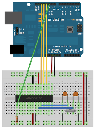
Wire up the Arduino board and microcontroller as shown in the diagram to the right. (in this case this link) https://www.arduino.cc/en/uploads/Tutorial/BreadboardAVR.png
-
Select “Arduino Duemilanove or Nano w/ ATmega328” from the Tools > Board menu. (Or “ATmega328 on a breadboard (8 MHz internal clock)” if using the minimal configuration described below.) For me, I chose the board called “Arduino Duemilanove or Diecimila”
-
Select “Arduino as ISP” from Tools > Programmer
-
Run Tools > Burn Bootloader. You should only need to burn the bootloader once. After you’ve done so, you can remove the jumper wires connected to pins 10, 11, 12, and 13 of the Arduino board.
Please note that for this step that you need to keep the IC that came with the board in its socket to copy the boot loader on to the new chip. When this is done successfully it should state “Bootloader Burn Complete” in the lower right. I would also recommend if you plan on doing a lot of these to do them all at once. If you plan on burning more ATMEGA328P in the future it might also be a good idea to make a shield to make the wiring quicker.
After the bootloader has been done successfully it is time to program. You will want to rewire your board to look as the following:https://www.arduino.cc/en/uploads/Tutorial/ArduinoUSBSerial.png. Please note that the original IC for the UNO will have to be removed. You will also want to change your Programmer back “AVR ISP” but keep the board as the “Arduino Duemilanove or Diecimila”. For my references to building and programming what I call the “Arduino Basic” I used the Arduino site for this, but I also used these 2 very good sources from YouTube.
DroneBot Workshop (long but very good in-depth example): Arduino Uno to ATmega328 - Shrinking your Arduino Projects - YouTube
GreatScott! (Short explanation but still very good) : Electronic Basics #6: Standalone Arduino Circuit - YouTube
The next step was to figure out how to use the IR sensor. For this reference, I again used YouTube and the same 2 channels. Here are those links:
DroneBot Workshop (long but very good in-depth example): Using IR Remote Controls with the Arduino - YouTube

GreatScott! (Short explanation but still very good): Control your LEDs with your TV remote?! || Arduino IR Tutorial - YouTube
Both examples use the <IRremote.h> library from Ken Shirriff to begin with and the example I began with was IRrecvDemo and can be found in the library manager when you type in “IR remote”. You will probably need to scroll through the options, but it should be there.
From example code I added the relay as an output and came up with this code:
/*
 * IRremote: IRrecvDemo - demonstrates receiving IR codes with IRrecv
 * An IR detector/demodulator must be connected to the input RECV_PIN.
 * Version 0.1 July, 2009
 * Copyright 2009 Ken Shirriff
 * http://arcfn.com
 */
#include <IRremote.h>

int RECV_PIN = 8;             // Puts the receive pin of the IR receiver to pin 8, which is pin 14 on IC
const int RELAY = 10;        //Put in signal pin of the relay to pin 10, pin 16 of the IC
int togglestate = 0;          // set to state of the switch to 0
IRrecv irrecv(RECV_PIN);
decode_results results;
void setup()
{
 Serial.begin(9600);            // Start serial monitor
 irrecv.enableIRIn();           // Start the receiver
 pinMode(RELAY,OUTPUT);         // declare RELAY to be an output
}
void loop() {

 if (irrecv.decode(&results)) {               // decodes the results
   Serial.println(results.value, HEX);        // shows the resulting as a hex number in the serial monitor
 switch(results.value){
  case 0x94CC5A5E:                            // Starts the case to look for the  results.value to be 94CC5A5E
  if(togglestate == 0){                       // if the toggle state is = to 0, turn RELAY PIN HIGH and toggle state to 0
    digitalWrite(RELAY,HIGH);
    togglestate = 1;
    delay(100);
  }
  else{
    digitalWrite(RELAY,LOW);                  // if the toggle state is = to 1, turn RELAY PIN LOW and toggle state to 1
    togglestate = 0;
    delay(100);
  }
break;                                        // breaks the case statement
 }
  irrecv.resume(); 	// Receive the next value
 }
}
Now for this project, I wanted switch something that used 120 VAC. If you have never work with 120 VAC please note you attempt this at your own risk! I have worked with 120VAC before, I have an electronics degree and am comfortable using it. The relay used in this circuit for this is also able to switch lower and safer DC voltages as well.
The parts list used in my project can be seen in the picture below.

Here is a picture of the wiring scheme I used.
And finally, here are some picture of the project parts and assembly.


