I am constructing an extended duration backup power solution for my home office computer system. I live in a rural area where power outages are common. A typical outage can last 1 to 1.5 hours. I need to be able to continue my work during these outages.
There are lots of UPS products on the market that are designed specifically for supplying backup power to computer systems. Unfortunately, UPS units with the capacity I require are very expensive. Therefore, I have concocted a hybrid solution that uses an affordable, low capacity, UPS for quick response time, and a large capacity inverter-battery unit to keep my computer system up and running for 2+ hours. See the diagram below.

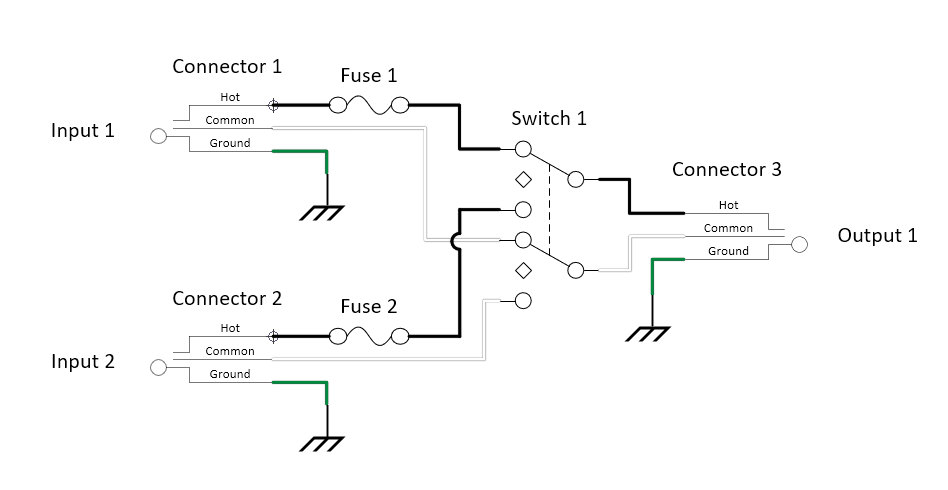
The computer system is connected to the UPS. The UPS is connected to utility power when available, or to inverter-battery power when utility power is unavailable. Therefore, when utility power fails, I need an easy way to transition UPS input power from utility power to inverter-battery power. I believe this can easily be done using a single DPDT, on-off-on, switch.
I prefer a manual solution as I do not plan on always having the inverter-battery unit active. When utility power is lost, I will turn on the inverter-battery unit and switch the UPS input power from utility power to inverter-battery power. When I turn on the inverter-battery unit, I can easily flip a switch to disengage the UPS from utility power and connect it to inverter-battery power.
How do I choose an appropriate DPDT, on-off-on, switch for my application? I’m using the DPDT switch as a source transfer switch. I have done some online research regarding DIY transfer switches and it has me a bit concerned. On the surface, it seems simple enough. Find a switch with adequate voltage and current ratings, and that is break-before-make. But what I’ve read seems to indicate that switching between two sources and a single load is very different than switching between a single source and two loads. I understand that a switch failure in the two source circuit is potentially more catastrophic than a switch failure in the single source circuit, but is the two source circuit any more likely to cause a switch failure than a single source circuit? Or, is it only that reliability is more critical as a failure is potentially catastrophic? Are there switches that are better suited for the two source circuit? If so, how do I identify such switches?
I’ve estimated my computer system as drawing roughly 150W to 200W. Therefore, the switch will be carrying a relatively low current load.
Thank you.