Q: Which MCU does Microchip use in E-Bikes, and how does it achieve the division of labor for real-time motor control and communication?
A: The current solution uses Microchip’s 4th-generation DSC products, such as the dsPIC33CK256MP505. However, the specific number of pins and peripherals used depends on customer requirements, while the MCU core remains the same. The dsPIC33CK has a main frequency of 200MHz (100 MIPS), and it only takes a little over a dozen microseconds to run a complete Field-Oriented Control (FOC) algorithm, leaving a large amount of idle time for communication tasks.
How to Divide Work for Real-Time Motor Control & Communication?
Microchip’s dsPIC33CK series (e.g., dsPIC33CK256MP505) is a type of Digital Signal Controller (DSC) that combines the general control capabilities of an MCU and the high-speed computing capabilities of a DSP, making it particularly suitable for real-time motor control.
Why Is a Single dsPIC33CK Sufficient?
- The dsPIC33CK has a main frequency of 200MHz and a computing efficiency of 100 MIPS.
- It only takes a bit over a dozen microseconds to run a complete FOC algorithm, which means the execution time occupancy rate of the control loop is very low, leaving a lot of idle time for handling other tasks.
- Due to the short time occupied by the FOC algorithm, the MCU can handle both control and communication tasks within the same chip without the need for an additional coprocessor.
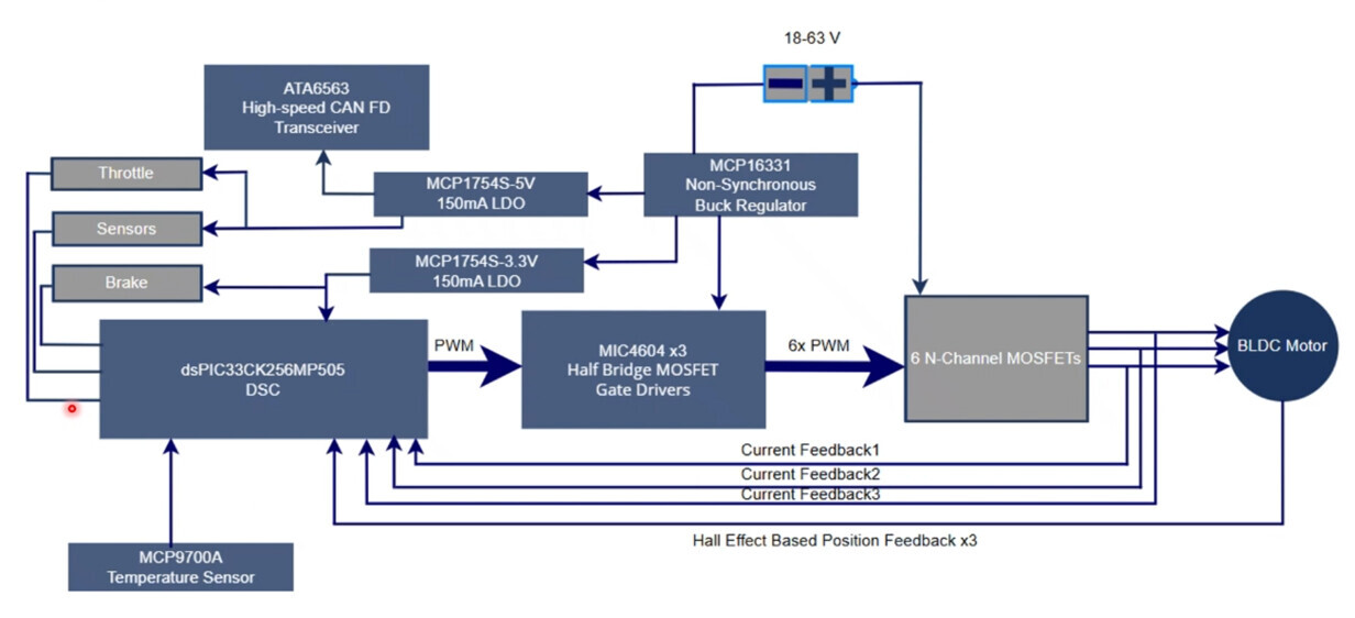
Motor Control System Block Diagram for Electric Bicycles (e-Bike)
Core Logic of the System (Block Diagram + Application Scenarios)
Functional Objectives
To achieve precise motor control of electric bicycles, covering modes such as manual, electric, and pedal-assisted. It supports efficient driving (FOC algorithm), short-term acceleration (field weakening technology), and energy recovery (regenerative braking), and is adaptable to complex scenarios such as urban commuting and hill climbing. In addition, it is equipped with on-board Flash for driving data recording.
Signal Flow (From Command to Motor Drive)
- Input Commands: Inputs from Throttle (accelerator/speed adjustment), Brake (braking), and Sensors (e.g., temperature sensor MCP9700A, Hall current sensor, and position sensors required for sensor-based FOC, which support Hall, magnetic encoder, inductive, resolver, etc.) are processed by the dsPIC33CK256MP505 DSC (Digital Signal Controller).
- Control Calculation: The DSC runs algorithms such as FOC and outputs PWM signals to the MIC4604 half-bridge gate drivers, which then drive the 6 MOSFETs to ultimately control the brushless DC (BLDC) motor.
- Power Supply and Communication: The MCP16331 Buck Regulator converts the 18-63V input to low voltage, and the MCP1754S LDO outputs 5V/3.3V to power the control circuit; the ATA6563 CAN FD transceiver enables high-speed communication (e.g., driving data, fault feedback).

More Content Related to FOC
- Why Use a DSP to Control a Three-Phase Permanent Magnet Synchronous Motor (PMSM)?
- 3 Motor Control Techs Comparison: FOC, V/f Control, Trapezoidal Six-Step Control (BLDC)
Related Products:
- Digital Signal Controller (DSC) — dsPIC33CK256MP508
- Gate Driver — MIC4104YM
- DC-DC Converter — MIC2129
- Regulator — MCP16301HT
- Low-Dropout Regulator (LDO) — MCP1826ST-3302E/DB
- CAN Transceiver — MCP2561-E/SN
- Serial Flash — SST25PF040C-40E
- Current Limiter — MIC2091-1YM5-TR
- Comparators — MCP6569T-E/ST
- Voltage Reference — LM4040CYM3-2.5-TR
- Operational Amplifiers (Op-AMPs) — MCP651ST-E/OT
More related Microchip E-Bike Tech Q&A:
- Microchip E-Bike Tech Q&A - How to Divide Work for Real-Time Motor Control & Communication?
- Microchip E-Bike Tech Q&A - How Is EV Speed Control Detected?
- Microchip E-Bike Tech Q&A - What is the scheme architecture of E-Bike?
- Microchip E-Bike Tech Q&A - How to Ensure Anti-Interference & Data Accuracy of Speed Acquisition?
- Microchip E-Bike Tech Q&A - How Does FOC Control Manage Battery Voltage & Current?
- Microchip E-Bike Tech Q&A - How to Prevent Thermal Runaway of E-Bike ?
- Microchip E-Bike Tech Q&A - How Does CPU Achieve Hardware Acceleration?
- Microchip E-Bike Tech Q&A - How to Prevent E-Bike Stall via Hardware Detection?
- Microchip E-Bike Tech Q&A - Which Components Need Monitoring to Ensure Stability?
- Microchip E-Bike Tech Q&A - Will E-Bike Positioning System Power Supply Interrupt?
- Microchip E-Bike Tech Q&A - What Components Are Provided?