Q: If multi-level sampling of speed is required, how do you ensure proper anti-interference performance and data accuracy of speed acquisition?
A: Adopt high-order filtering algorithms or phase-locked loop (PLL) solutions .
Why Does Multi-Level Speed Sampling Cause Interference Issues?
Multi-level sampling (or multi-rate sampling) refers to the scenario where speed signals may be collected or processed at different frequencies in the same control system. In sensorless control, speed signals are estimated through motor models and observation algorithms, and they inherently superimpose interferences such as electrical noise, PWM ripples, and current sampling errors.
If these “noisy” speed estimation values are directly fed into the controller—especially in the low-frequency loops of multi-level sampling—noise will be amplified or accumulated, leading to unstable control.
Role of High-Order Filtering Algorithms
High-order filters (e.g., second-order low-pass filters, Kalman filters, sliding mode filters) can effectively suppress high-frequency noise while retaining the dynamic characteristics of speed.
Key points for filter design:
- The cutoff frequency should be low enough to filter out PWM and high-frequency ripple noise.
- The delay should be small enough to avoid introducing phase lag that makes the control system sluggish.
Anti-Interference Performance and Accuracy of PLL (Phase-Locked Loop) for Multi-Level Speed Sampling
The block diagram of a PLL (Phase-Locked Loop) typically includes three core modules: Phase Detector (PD), Loop Filter (LF), and Voltage-Controlled Oscillator (VCO). In some scenarios, a frequency divider or signal preprocessing unit may be added. Its core logic is to achieve accurate synchronization between the “input signal frequency/phase” and “output signal frequency/phase” through closed-loop feedback.
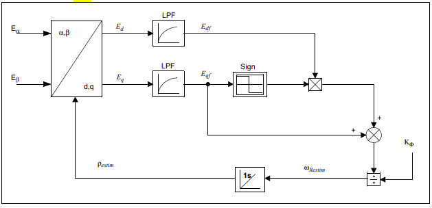
Image source: Microchip
Functions of PLL Modules
- Phase Detector (PD): Compares the estimated rotor position with the phase of the observed voltage signal.
- Loop Filter (LF): Acts as a low-pass filter to eliminate high-frequency noise.
- Voltage-Controlled Oscillator (VCO) or Integrator: Adjusts the speed and position estimation based on the filtered output.
The core logic of the PLL (Phase-Locked Loop) is to achieve accurate synchronization between the “input signal frequency/phase” and “output signal frequency/phase” through closed-loop feedback.
More Content Related to FOC
- Why Use a DSP to Control a Three-Phase Permanent Magnet Synchronous Motor (PMSM)?
- 3 Motor Control Techs Comparison: FOC, V/f Control, Trapezoidal Six-Step Control (BLDC)
Related Products:
- Digital Signal Controller (DSC) — dsPIC33CK256MP508
- Gate Driver — MIC4104YM
- DC-DC Converter — MIC2129
- Regulator — MCP16301HT
- Low-Dropout Regulator (LDO) — MCP1826ST-3302E/DB
- CAN Transceiver — MCP2561-E/SN
- Serial Flash — SST25PF040C-40E
- Current Limiter — MIC2091-1YM5-TR
- Comparators — MCP6569T-E/ST
- Voltage Reference — LM4040CYM3-2.5-TR
- Operational Amplifiers (Op-AMPs) — MCP651ST-E/OT
More related Microchip E-Bike Tech Q&A:
- Microchip E-Bike Tech Q&A - How to Divide Work for Real-Time Motor Control & Communication?
- Microchip E-Bike Tech Q&A - How Is EV Speed Control Detected?
- Microchip E-Bike Tech Q&A - What is the scheme architecture of E-Bike?
- Microchip E-Bike Tech Q&A - How to Ensure Anti-Interference & Data Accuracy of Speed Acquisition?
- Microchip E-Bike Tech Q&A - How Does FOC Control Manage Battery Voltage & Current?
- Microchip E-Bike Tech Q&A - How to Prevent Thermal Runaway of E-Bike ?
- Microchip E-Bike Tech Q&A - How Does CPU Achieve Hardware Acceleration?
- Microchip E-Bike Tech Q&A - How to Prevent E-Bike Stall via Hardware Detection?
- Microchip E-Bike Tech Q&A - Which Components Need Monitoring to Ensure Stability?
- Microchip E-Bike Tech Q&A - Will E-Bike Positioning System Power Supply Interrupt?
- Microchip E-Bike Tech Q&A - What Components Are Provided?