The block diagram of a PLL (Phase-Locked Loop) typically includes three core modules: a Phase Detector (PD), a Loop Filter (LF), and a Voltage-Controlled Oscillator (VCO). In some scenarios, a frequency divider or signal preprocessing unit may be added. Its core logic is to achieve precise synchronization between the frequency/phase of the input signal and the frequency/phase of the output signal through closed-loop feedback:
I. Principle of PLL (Phase-Locked Loop)
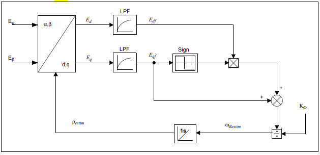
(Image source: Microchip)
The core logic of a PLL (Phase-Locked Loop) is to achieve precise synchronization between the frequency/phase of the input signal and the frequency/phase of the output signal through closed-loop feedback:
- Phase Detector (PD): Compares the phase difference between the input speed-related signal (e.g., motor current alternating signal, encoder pulse signal) and the output signal of the VCO, and converts this phase difference into an error voltage.
- Loop Filter (LF): Filters the error voltage (e.g., via low-pass filtering) to suppress high-frequency noise and transient interference, and outputs a smooth control voltage.
- Voltage-Controlled Oscillator (VCO): Adjusts the frequency/phase of the output signal according to the control voltage, making it gradually approach the characteristics of the input signal. Finally, it achieves “phase locking” — the input and output signals have the same frequency and a stable phase difference.
II. Why Can PLL and High-Order Filtering Ensure Anti-Interference and Accuracy in Multi-Level Speed Sampling?
Multi-level speed sampling needs to address issues such as differences in signal characteristics at different speeds (e.g., weak signals at low speeds, high-frequency signals at high speeds), environmental electromagnetic interference, and sensor noise. PLL and high-order filtering solve these challenges from different dimensions:
1. PLL (Phase-Locked Loop) Solution: Eliminating Frequency Mismatch and Dynamic Errors Through Synchronous Tracking
In multi-level speed sampling, changes in rotational speed cause large fluctuations in the frequency of related signals (e.g., current, pulses). The core value of a PLL lies in dynamically locking the signal frequency to ensure that sampling matches the real-time characteristics of the signal:
- Suppressing Frequency Aliasing: According to the Nyquist sampling theorem, the sampling frequency must be at least twice the maximum frequency of the signal. The PLL dynamically adjusts the sampling clock frequency through the VCO, ensuring it always tracks the frequency of the input signal. This avoids redundant oversampling in the low-frequency range or undersampling aliasing in the high-frequency range caused by a fixed sampling rate.
- Resisting Dynamic Interference: When the speed changes suddenly (e.g., during multi-level switching), the frequency of the input signal fluctuates drastically. The loop filter of the PLL can smooth the error signal, and the VCO responds quickly to adjust the output frequency, ensuring stable signal tracking even during the transition process.
- Reducing the Impact of Phase Noise: Environmental electromagnetic interference can cause signal phase jitter. The closed-loop feedback of the PLL can offset this jitter through phase correction, keeping the phase of the output signal stable.
Conclusion
The core challenges of multi-level speed sampling are dynamic fluctuations in signal frequency and interference noise contamination. The PLL ensures real-time synchronization between sampling and signal characteristics through frequency tracking and phase locking, eliminating dynamic mismatch errors.
Related Products
Related Application Notes
More Content Related to FOC
- Why Use a DSP to Control a Three-Phase Permanent Magnet Synchronous Motor (PMSM)?
- 3 Motor Control Techs Comparison: FOC, V/f Control, Trapezoidal Six-Step Control (BLDC)
- Why Use the Field-Oriented Control (FOC) Algorithm?
- What is the Clarke Transformation in the Field-Oriented Control (FOC) Algorithm?
- What is the Park Transformation in the Field-Oriented Control (FOC) Algorithm?
- Why Can PLL (Phase-Locked Loop) Ensure Anti-Interference and Accuracy in Multi-Level Speed Sampling?