The Park Transformation is a core algorithm in the Field-Oriented Control (FOC) of AC motors. The essence of the Park Transformation lies in projecting the AC current in the stationary coordinate system onto the synchronous rotating coordinate system and converting it into a DC component that can be stably controlled. This transformation enables AC motors to be precisely controlled like DC motors, serving as the cornerstone of high-performance motor control (e.g., in electric vehicles and industrial drives).
Core Logical Framework of Sensorless Field-Oriented Control (FOC) for PMSM

(Image source: Microchip)
1. Principle of the Park Transformation
The Park Transformation is a core step in Field-Oriented Control (FOC), solving the problem of precise control of AC motors:
- AC to DC Conversion: It converts the sinusoidal AC current in the αβ axis into constant DC current in the dq axis, allowing PI regulators (which enable static-error-free tracking of DC signals) to precisely adjust the current;
- Decoupling Control:
- Id is responsible for adjusting the motor flux linkage (e.g., in permanent magnet synchronous motors (PMSMs), Id enables torque maximization control);
- Iq directly determines the motor torque (Iq is proportional to torque and is the core of speed control). After decoupling, flux linkage and torque can be adjusted independently without mutual interference.
The figure below illustrates the principle of the Park Transformation through formulas + vector diagrams:
Park Transformation Principle Block Diagram
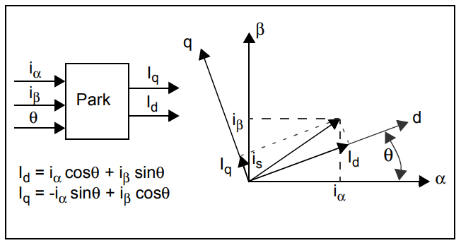
(Image source: Microchip)
The vector diagram on the right intuitively shows the projection process of the current vector:
- is: The space vector of the stator current (its amplitude equals the effective value of the current, and its direction rotates with time at a frequency equal to the electrical frequency).
- iα, iβ: The stationary projections of is on the α-axis and β-axis (they rotate with is and are always sinusoidal AC currents).
- Id, Iq: The projections of is on the synchronously rotating d-axis and q-axis:
- Since the dq-axis rotates synchronously with the rotor, if the motor operates in a steady state (constant speed), Id and Iq will become constant DC quantities (this is the core value of the Park Transformation!).
2. Coordinate System Background of the Park Transformation: αβ (Stationary) vs. dq (Rotating)
-
αβ Coordinate System: A stationary coordinate system bound to the motor stator:
- The α-axis is aligned with the axis of the stator’s phase-A winding;
- The β-axis leads the α-axis by an electrical angle of 90° (counterclockwise direction), forming a 2D plane. The projections of the stator current vector is on the αβ-axis are iα (α-axis component) and iβ (β-axis component), which are AC currents that vary sinusoidally with time (at a frequency equal to the motor’s electrical frequency).
-
dq Coordinate System: A synchronously rotating coordinate system bound to the motor rotor:
- The d-axis is usually aligned with the flux linkage direction of the rotor (e.g., in PMSMs, the d-axis is aligned with the main flux linkage generated by permanent magnets; in induction motors, the d-axis is aligned with the stator flux linkage);
- The q-axis leads the d-axis by an electrical angle of 90° (counterclockwise direction) and rotates synchronously with the rotor (the rotational angular velocity equals the rotor’s electrical angular velocity ωe). The rotation angle of the dq-axis is described by the electrical angle θ: θ is the angle between the d-axis and the α-axis (it changes with time, following θ = ωet).
3. Mathematical Formula of the Park Transformation: From αβ to dq
The formulas on the left side of the diagram define the transformation relationship:

- Physical Meaning: It projects the currents iα and iβ (in the stationary αβ-axis) onto the synchronously rotating dq-axis, resulting in the d-axis current Id and q-axis current Iq.
- Formula Derivation Logic (Geometric Projection): Taking the d-axis as an example:
- iαcosθ: The projection of iα (α-axis current) onto the d-axis;
- iβsinθ: The projection of iβ (β-axis current) onto the d-axis (since the angle between the β-axis and α-axis is 90°, the angle between the β-axis and d-axis is (90°−θ), so the projection is iβcos(90°−θ) = iβsinθ). The derivation for the q-axis is similar. The negative sign comes from the direction of the q-axis: when θ=0, the q-axis is aligned with the β-axis. Substituting θ=0 into the formula for Iq to verify: Iq = −iα⋅0 + iβ⋅1 = iβ, which matches the expected result.
In short: Without the Park Transformation, the current of an AC motor is high-frequency AC, which cannot be stably controlled by a PI regulator; with it, AC motors (such as permanent magnet synchronous motors (PMSMs) and induction motors (IMs)) can be precisely controlled just like DC motors.
Related Products
Related Application Notes
More Content Related to FOC
- Why Use a DSP to Control a Three-Phase Permanent Magnet Synchronous Motor (PMSM)?
- 3 Motor Control Techs Comparison: FOC, V/f Control, Trapezoidal Six-Step Control (BLDC)
- Why Use the Field-Oriented Control (FOC) Algorithm?
- What is the Clarke Transformation in the Field-Oriented Control (FOC) Algorithm?
- What is the Park Transformation in the Field-Oriented Control (FOC) Algorithm?
- Why Can PLL (Phase-Locked Loop) Ensure Anti-Interference and Accuracy in Multi-Level Speed Sampling?