Introduction
To safely utilize lithium-ion or lithium polymer batteries, they must be paired with protection circuitry capable of keeping them within their specified operating range. The most important faults that the batteries must be protected from are overvoltage, overcurrent, and over temperature conditions as these can place the batteries in a dangerously unstable state. The same is true for undervoltage conditions, though to a lesser extent. Thus undervoltage protection is often only included in the primary layer of protection, but not the secondary layer. Since modern primary protection ICs are designed to be as flexible and fully-featured as possible, finding a simple, inexpensive undervoltage protection solution that doesn’t require firmware control is not as easy as it should be. A similar issue presents itself when trying to incorporate overcurrent protection that is more sophisticated than a fuse, yet does not come bundled with unnecessary battery management functionality.
Background
Lithium-ion (Li-ion) and lithium polymer (LiPo) batteries have very similar electrical characteristics but differ in packaging. Li-ion batteries are made with a rigid (typically cylindrical) casing while LiPo batteries come in pouches of various sizes. Due to their high energy density, these batteries are widely favored for use in applications with weight and/or space restrictions. Compared to other battery chemistries, they require less maintenance [1] and have a higher output voltage per cell (which means few cells have to be used). Unfortunately, due to their sensitive nature, protection circuitry is required to ensure that these cells are not used outside of their prescribed operating limits. Failing to do so can literally have explosive results. Figure 1 shows a block diagram of a typical battery management system (BMS) which includes the battery protection blocks as well as a battery monitoring block.

Notice that there are two layers of protection in the BMS above. The primary protection is composed of the “Balancing and Primary Safety” block and the “Protection MOSFETS” block. The secondary protection is composed of the “Secondary Safety”, “PTC”, “TCO”, and “Nonresettable Fuse” blocks. Often, the primary protection and gas gauge components are combined into a single IC which may include additional protection features not shown above like over/under temperature protection and battery authentication. The elements of a BMS may be integrated into the battery pack (pack side), into the application itself (system side), or some combination of the two.
Undervoltage Is Underrated
If the voltage across a Li-ion/LiPo cell is allowed to fall below its minimum operating value (typically around 2.5V or 3.2V depending on the exact cell), the cell will be damaged. To what extent depends on how over depleted the cell is allowed to get and how long it stays over depleted. In the best case, when the voltage falls only slightly below the minimum, there will be a minor loss in capacity and the self-discharge rate will increase. The lower the cell voltage gets, the more pronounced these effects become. If the cell voltage gets too low, then it becomes dangerous to attempt to recharge the cell because it may develop a short and cause severe damage to its surroundings [3]. Despite these concerns, many BMSs do not include redundant undervoltage protection.
The example BMS in Figure 1 provides overvoltage protection in the “Secondary Safety” block, but not undervoltage protection. This is more than likely due to the fact that a non-resettable fuse is blown by the “Secondary Safety” block when it detects a fault. If undervoltage protection were included in this scheme and any of the cells became slightly over discharged, then the entire pack would be rendered useless even though minimal damage was incurred. The obvious solution to this problem is to lower the undervoltage threshold at the secondary protection stage, thereby only protecting from a severe over discharge condition. Unfortunately, many secondary protection ICs come with preset thresholds that may not be low enough for this kind of protection. Another option would be to use a high-side switch in place of the non-resettable fuse if the application would allow it. If not, both the fuse and switch could be used where the fuse is blown by the overvoltage alert signal and the switch is closed by the undervoltage alert signal. These arrangements would leave the overvoltage protection intact while the added undervoltage protection would prevent premature cell wear in the case of an error in the primary protection component.
Secondary protection should be simple in the sense that no firmware configuration is required. Most primary protection ICs include a serial communication interface that allows a host to set voltage thresholds, configure alert settings, read status flags, and even read the most recent measurements. This functionality is not required by the redundant protection because, ideally, this protection will never be used. Any settings should be pin configurable and the ICs themselves should be small and inexpensive. For single cell applications, these requirements are very simple to meet because a basic window comparator can provide secondary over/undervoltage protection. Consider the TPS3700 window comparator from TI, which allows the thresholds to be set via an external resistor divider network and includes an internal 400mV reference voltage [4]. The block diagram in Figure 2 is adapted from the TPS3700 datasheet to show how the resistor values can be chosen to set the overvoltage threshold to 4.3V and the undervoltage threshold to 2.5V.

For multicell applications, a single window comparator should not be used because the voltage across each cell needs to be monitored individually. This can be accomplished with Maxim’s MAX11080IUU+ battery pack fault monitor, which provides both overvoltage and undervoltage protection for up to 12 cells. If more cells are required, then multiple chips can be daisy-chained together. The overvoltage and undervoltage thresholds are pin selectable and the alert delay can be set via an external capacitor [5]. Though this IC does work with lower cell counts, its higher cost and large footprint make it better suited for high voltage applications. In fact, its operating voltage is specified at 6V to 72V [5], meaning applications using two cells will not work with this device.
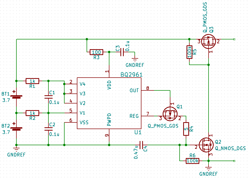
As it turns out, it is no simple task finding a simple over/undervoltage protection IC that can monitor two cells independently. Luckily, TI offers the BQ296xxx line of overvoltage protection ICs for 2-4 cells. These devices include a regulated 3.3V output supply that is disabled when any of the cells fall below the undervoltage threshold, thus avoiding over discharging the batteries. This output is intended for supplying power to low-power circuitry (less than 1mA) like an RTC [6], but it can also be utilized as an active-low undervoltage detection signal. Unlike the two previously presented solutions, the overvoltage and undervoltage thresholds of this device are not configurable. Rather, they are pre-programmed at the factory and identified by the part number of the device. For example, the BQ296113 has an overvoltage threshold of 4.35V and an undervoltage threshold of 2.5V while the BQ296107 has an overvoltage threshold of 4.5V and an undervoltage threshold of 2.8V. A summary of these device options can be found on Tables 1 and 2 in the datasheet [6]. Figure 3 shows how both the overvoltage fault signal and the regulated output can be interfaced with a high-side switch.
Adding Overcurrent Protection
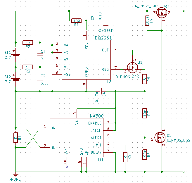
The regulated output of the BQ296xxx can be used to easily integrate other battery protection devices that have an active-low fault detection signal. As an example, consider the INA300 current-sense comparator. This IC has an active-low, open-drain alert signal and consumes, at the most, 135µA [7] (well below the 1mA limit). Figure 4 shows the modified schematic that provides overvoltage protection, undervoltage protection, and discharge overcurrent protection for two cells in series. The concept is simple: the alert signal will be logic high when there is no fault condition and logic low when there is a fault condition either on the INA300 or the BQ296xxx. If an overcurrent condition occurs, the INA300 will still be powered and it will pull the alert signal low. If an overvoltage or undervoltage condition occurs, the INA300 will be disconnected from the regulated output of the BQ296xxx and the alert signal will be pulled low by R8.
The value of R8 must meet the following condition: R8 ≥ \frac{V_t \cdot R7}{3.3 - V_t},where Vt is the threshold voltage of Q2.
The INA300 has many pin configurable option that allow the designer to tailor its behavior to the requirements of the application. Most importantly, the overcurrent threshold can be set by choosing the value of the external resistor connected to pin 3 as follows:
Other options that can be configured are the output mode, alert delay, and hysteresis: all of which are summarized in Table 1. The output mode can be set to either transparent mode where the alert signal is continuously updated to match the overcurrent state, or to latch mode where the alert signal must be manually cleared after a fault is detected. The alert delay setting determines how long the overcurrent condition must be present before the alert signal is set. Choosing the smallest 10µs delay means the device will respond quickly to a fault condition, but is more prone to false alerts caused by noise. As the delay is increased, the device becomes more resilient towards noise at the expense of a slower response time. Note that if 10µs is chosen as the alert delay setting, a noise adjustment factor (NAF) must be included in the RLIMIT calculation to make the overcurrent threshold more accurate (see the datasheet for more information). Lastly, the hysteresis setting determines how far the overcurrent threshold will be lowered once an overcurrent fault is detected [7].
Table 1: INA300 configuration options [7]
| Pin State | Output Mode (pin 6) | Alert Delay (pin 7) | Hysteresis (pin 10) |
|---|---|---|---|
| Float | Not Valid | 10µs | 2mV |
| GND | Transparent Mode | 50µs | 4mV |
| VS | Latch Mode | 100µs | 8mV |
Conclusion
Whether using Li-ion or LiPo cells, a battery management system is required to ensure that they are used safely and not worn out prematurely. Because undervoltage is not the most critical fault condition that needs to be detected (compared to overvoltage, overcurrent, and over temperature), it is generally difficult to find a simple device that implements undervoltage protection for each cell individually and does not include a host of unnecessary functionality. Fortunately, there are a variety of options available meeting these requirements that differ depending on the number of cells used in the application. Should overcurrent protection need to be added alongside the chosen protection scheme, the INA300 current-sense comparator is an excellent choice due to its flexibility and simplicity.
Related Topics
Li-ion / LiPo Battery Storage and Permanent Capacity Loss
Important Precautions for Proper Handling, Storage, & Use of Hybrid Lithium Supercapacitors
References
[1] Cadex Electronics Inc., “Is Lithium-ion the Ideal Battery?,” [Online]. Available: http://batteryuniversity.com/learn/archive/is_lithium_ion_the_ideal_battery. [Accessed 18 May 2017].
[2] D. Gunderson, “Designing battery-management systems,” Micro Power Electronics, 6 January 2011. [Online]. Available: http://www.edn.com/design/power-management/4363929/Designing-battery-management-systems. [Accessed 18 May 2017].
[3] Woodband Communications Ltd, “Lithium Battery Failures,” [Online]. Available: http://www.mpoweruk.com/lithium_failures.htm. [Accessed 18 May 2017].
[4] Texas Instruments, “TPS3700 Window Comparator With Internal Reference for Overvoltage and Undervoltage Detection,” TPS3700 datasheet, February 2012 [Revised February 2017].
[5] Maxim, “12-Channel, High-Voltage Battery-Pack Fault Monitors,” MAX11080 datasheet, April 2009 [Revised June 2010].
[6] Texas Instruments, “bq296xxx Overvoltage Protection for 2-Series, 3-Series, and 4-Series Cell Li-Ion Batteries with Regulated Output Supply,” BQ2961 datasheet, February 2014 [Revised January 2017].
[7] Texas Instruments, “INA300 Overcurrent-Protection, Current-Sense Comparator,” INA300 datasheet, February 2014 [Revised April 2016].