The purpose of a thermal interface material is to fill gaps between mating surfaces with a substance that’s got better thermal conductivity than the air that would typically fill those gaps otherwise, in order to improve heat transfer between the two surfaces. The difference can be significant, as typical TIMs conduct heat roughly 100 times better than the air they displace. A variety of products adapted for different use cases are available, and the purpose of this page is to provide an overview of available options and inform the process of choosing and using a TIM.
For those who may be interested, products of the kind being discussed are found in two product families at Digi-Key, based on the consistency of the product as sold. The fluid-like, tube-o-goop sort of products are listed in the Thermal - Adhesives, Epoxies, Greases, Pastes family, and solid-like, sheet-form products are listed in the Thermal - Pads, Sheets family, both of which are filed under the Fans, Thermal Management product category.

Figure 1. (L-R) Surface of a commercial heatsink surface at progressively higher magnifications, showing tool marks that create a rough surface and a need for a thermal interface material.
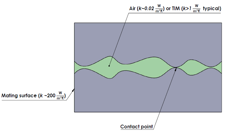
Figure 2. Diagram of a thermal interface cross section, with typical thermal conductivity ( k ) values of the different components.
Categories and Flavors of TIMs
Greases, Gels, Putties & Pastes
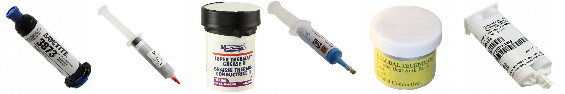
Figure 3. A variety of products in the thermal grease family. (images not to scale)
Thermal greases, gels, putties, and pastes are a class of thermal interface materials that are produced as room-temperature fluids, usually having a consistency similar to a soft butter or toothpaste. Though some of these products are designed to cure or harden into more of a rubbery consistency after application, many are intended to remain fluid throughout their working lives. Terminology within this realm of products is not especially clear or well adhered to in practice, so some extra attention to understand the specific nature of any given product is needed. In general however, a “grease” is a non-curing product used in thin layers to aid thermal transfer between surfaces that are nominally flat and smooth, whereas a “putty” tends to be a material used at greater thicknesses to fill gaps between irregular surfaces or those that are not in direct physical contact with each other.
The fluid nature of these products is simultaneously their great advantage and disadvantage; by being able to flow readily during assembly, they tend to be forgiving of application variables and amenable to automated application. On the other hand, like any other greasy substance they can be extremely messy to handle and a ready source of process contamination. The fluidizing components of these materials (particularly silicone-based products) are also known to migrate out of a joint over time, with attendant loss of performance as the grease effectively dries out, leaving the solid components behind as a crusty substance that lacks the ability to flow in response to movement between the surfaces, such as might be caused by thermal expansion, vibration, etc. In the case of products that cure to a firmer consistency, the potential for messiness remains, and though the curing process largely solves the dry-out issue, it tends to make any re-work, test probing, or repair of areas to which it is applied more problematic, especially when the material used has strong adhesive qualities.
Products of this type are electrically non-conductive in general, though some are specifically designed to be conductive and will cause problems if allowed to bridge nodes in a circuit that aren’t supposed to be connected. While typical applications of these products do not rely on their electrical properties, users are advised to take note of these properties and consider any potential effects if placed in contact with an electrically active node, or used in applications where their dielectric properties could affect circuit performance.
Phase-Change Materials (PCMs)

Figure 4. A sampling of phase-change TIM products. (images not to scale)
Phase-change materials are a class of TIMs that change from a solid to a viscous liquid at relatively low temperatures, usually in the neighborhood of 55~65°C, and which are generally used as an alternative to grease-type products. Their characteristic phase-changing property allows the convenience of handling and processing the materials as solids at room temperature, while maintaining the conformability and wetting properties of a fluid at elevated operating temperatures. Relative to grease-type products, PCMs have many favorable attributes; they’re much neater to handle in manual assembly processes, generally don’t suffer from dry-out issues, and can be pre-applied for later assembly, all while offering thermal performance comparable to grease-type products. Disadvantages of PCMs relative to grease type products in general would include a lower tolerance for misapplication and a higher product cost.
PCMs are available in a number of forms, including bulk sheets and rolls, shapes pre-cut from the same to fit specific device packages, deodorant-like sticks for rub-on application, and dispensable fluids designed to dry or harden into a solid phase-changing material after initial application. The sheet- and shape-type products will often combine a PCM with other materials to provide desirable properties such as improved structural integrity for ease of handling or a reliable electrical insulation characteristic, and such products will often be found categorized as “thermal pads” or something similar.
Adhesives & Potting Compounds

Figure 5. A sampling of thermal adhesive products. (images not to scale)
Thermal adhesives are simply specialized glues designed to do a respectable job of heat transfer while sticking stuff together, and are available as pressure-sensitive sheets or tapes and also as curing fluids. Thermal potting compounds by contrast, are primarily designed for protective encapsulation while facilitating heat transfer from a system’s innards to an outer shell, and are sold in fluid form. Products that are initially fluid can have a range of mechanical and adhesive properties once cured; some hardly stick to surfaces they’re applied to at all and can be readily peeled away when cured, some exhibit a more moderate adhesion, and others are designed to stick permanently. Some products have a soft, rubbery texture when cured and are easily torn much like like a firm cheese, whereas others cure to a relatively hard and inflexible state.
Advanced materials

Figure 6. A sampling of graphite-based TIM products. (images not to scale)
One relatively new class of thermal materials based on a form of carbon known as pyrolytic graphite has the interesting property of being thermally anisotropic; its properties vary depending on the direction through the material in which they’re measured. Through its thickness a sheet of the stuff can conduct heat about as well as most TIMs. In-plane however, its thermal conductivity is extremely good, on the order of 3 to 8 times better than aluminum. The base material itself is quite flexible as a thin sheet, exhibits a modest electrical conductivity, and through various lamination and compositing processes has been adapted to create different products adapted to the various “thermal pad” concepts outlined below, with varying electrical conductivity characteristics, mechanical, and adhesive properties. Because of their unique qualities, these graphite-based materials lend themselves well to moving heat around in the tight confines of portable consumer devices, and other applications where a highly engineered thermal management solution is needed.
What exactly is a “thermal pad” anyway?
The concept of a “thermal pad” in electronics circles is a bit vague; the term seems to be used and understood in reference to most any non-fluid substance or object that one might place between a heat-generating device and a heatsink, for any number of reasons. There are a number of distinct product types under that umbrella however, which serve different purposes and are not interchangeable. Loosely speaking, they fall into 3 categories:
1. Stuff designed to go between well-matched surfaces when electrical insulation between them does not matter. The purpose of these products is to facilitate heat transfer, and little else. When encountered as a “pad” these will often be phase-change materials, sold in bulk sheet or roll format or sometimes pre-cut to fit a particular IC package. They can offer thermal performance comparable to that achievable with grease-type products without the mess, and are typically the thinnest pad-type materials on offer.

Figure 7. Example of an application where an electrically insulative TIM is not required.
2. Stuff designed to go between well-matched surfaces when electrical insulation between them does matter. Materials of this sort are often composites, consisting of an electrically insulating material laminated or coated on both sides with a thermal transfer material. They’re the sort of product one uses when a design requires that a thermal transfer path –not- also be electrically conductive, lest Bad Things happen. Somewhat thicker on average than their electrically non-insulting kin, they’re available in similar forms and can be difficult to discern from them based on product images. Thermally however, electrically insulating TIMs tend to perform 2-5 times poorer than their non-insulating kin, and for this reason are not recommended if the need for electrical isolation can be reasonably avoided. Additionally, the clamping pressures required to achieve optimal thermal performance with these products can be quite high, making the system’s mechanical stress tolerance a factor in the thermal performance that can be achieved.
It should be noted that products whose primary function is to provide electrical insulation between a device package and a mounting surface sometimes end up classified as thermal pads, if their composition gives at least a passing nod to facilitating thermal transfer. Frequently used in conjunction with a thermal grease to reduce interfacial thermal resistances, the mica insulators routinely found underneath transistors in metal can TO-3 packages are a common example.

Figure 8. Example of an application where an electrically insulative TIM is commonly used.
3. Stuff designed to go between poorly matched surfaces. These are designed to fill large, irregular gaps such as that between a component-bearing PCB surface and an enclosure wall. The resulting thermal transfer performance is better than that yielded by an unfilled air gap, which is like saying that it’s better than a sharp stick in the eye; “Better” does not necessarily mean “good.” They are compliant, solid materials that can measure 10mm or more in uncompressed thickness, and which might be chosen in place of a thermal putty or potting compound, where greater ease of reentry, rework, or cleanliness of assembly is desired. Due to the size of the gaps these products are typically called upon to fill, the thermal transfer performance of interfaces incorporating them is typically the poorest among the three classes of “thermal pads” described here. They should not be used between well-matched surfaces.

Figure 9. Cutaway view of an application where a gap-filling material might be used.
TIM selection criteria
Electrical insulation characteristics
If an application calls for an electrically insulating thermal interface between two surfaces, the list of available options shrinks significantly. While many TIMs are not particularly good electrical conductors in and of themselves, they also lack the mechanical properties needed to reliably prevent direct contact between mating surfaces; a thin layer of grease is hardly an impenetrable wall, and burrs, ridges, or debris left from forming or machining processes can easily penetrate soft/thin materials when a clamping force is applied.
A common solution in this case is the use of a combination of materials; one providing an electrical insulation barrier and another providing a thermal interface function. Historically, mica insulators with silicone-based thermal grease on both sides were a common solution, though newer materials with improved handling and thermal properties have since become available and preferred. These products may consist of ceramic-filled fiberglass and various polymers, polyimide/silicone rubber laminates, and similar solutions.
Mechanical factors
Material thickness
An ideal TIM thickness is one that completely fills the voids and spaces between mating surfaces, without producing any unnecessary separation between them. In the case of nominally flat & smooth surfaces, appropriate materials tend to be about 0.02" (0.5mm) or less in uncompressed thickness, whereas materials designed for use with irregular surfaces or for gap-filling applications are generally much thicker. These gap-filling applications tend to base material thickness choices on the extreme values of the gaps to be filled; a material thick enough to fill the largest gap is desired, without requiring excessive force to squeeze it into the thinnest of the gaps in the system. Particularly with the solid, pad-type gap filling materials, the forces needed to compress the material into place can cause a circuit board to flex, which can result in component damage, solder joint failure, or other similar unpleasantness. Take such possibilities into account when making selections for a gap filling material thickness, composition, and placement.
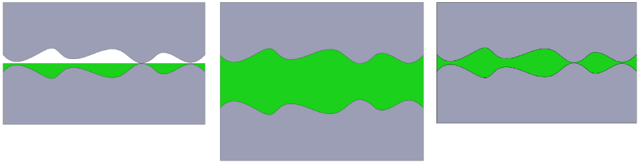
Figure 10. (L-R) Illustrations of insufficient, excess, and ideal TIM thickness

Figure 11. Board flexure due to excess gap-filling material can cause component damage.
In thin-material cases, flatness and surface roughness specifications guide selection of an ideal TIM thickness. Better datasheets offer both, though flatness specs tend to be dominant and are often given alone for that reason. Because the exact geometries of any surface curvature usually aren’t specified and the values given are often limiting maximums (meaning that actual values are better than the number given) it’s difficult to calculate -the- optimal TIM thickness in most cases, and some experimentation may be needed. Grease-type products, being capable of flowing under pressure, are often applied slightly thicker than needed and the excess squeezed out of the joint during application to ensure that the grease thoroughly wets the applied surfaces. A grease layer thickness equal to the sum of the flatness specs for the two surfaces is a good starting point, which should minimize the mess resulting from over-application.
Pad-type solid materials call for a bit more thought; being non-fluid, excess material isn’t simply going to squirt out the side of a joint to be wiped up after assembly. On the other hand, the available material thicknesses tend to be much more quantized, and the options available limited by manufacturer’s offerings. Take into account the behavior of the material and the geometry of the mating surfaces, and pick a TIM thick enough to fill the gaps. Using a phase-changing material? The stuff can melt and redistribute itself as needed, so the sum-of-flatness-specs guideline suggested for grease-type products is a reasonable starting point, provided that the application will reach the material’s melting temperature and that clamping force can be maintained when it does so. Using an electrically insulating TIM? These are often laminates of an electrical insulator with a more proper TIM on both sides, and the insulator’s thickness doesn’t count toward filling gaps between the mating surfaces. Use surface geometry information to guide material selection based on the thickness of the conformal, electrically non-insulating layers of the material. A conformal-layer thickness equal to the larger of the flatness specs of the two surfaces is a good starting point in this case.
Note that the above suggestions assume surface flatness specs that are much larger than the roughness specs. If the opposite is true use roughness figures instead, or the sum of roughness and flatness if the dimensions of the two are comparable.

Figure 12. Illustration of surface roughness and flatness.
Fastening method
The manner in which the mating surfaces are to be mechanically fastened together has some influence on TIM selection. TIMs with adhesive qualities are available, and can address both heat transfer and mechanical fixation problems at the same time. Because of the vulnerabilities to mechanical shock and vibration that come with simply gluing a heatsink onto a device with no other support, this approach isn’t recommended if a lot of thermal energy needs to be transferred (implying a large, heavy heatsink) or where significant jostling or vibration is expected.
Another mechanical fastening approach is the use of threaded fasteners. Though familiar and effective, some attention to detail is required to achieve a consistent clamping pressure during initial assembly and over a service life. Screw hardware also tends to be relatively expensive and cumbersome to assemble; the holes need to line up properly in 3-dimensional space, often to within a few hundredths of an inch (~1mm) or less and there are numerous small parts involved, more so in cases where electrical insulation between the mated surfaces needs to be maintained.

Figure 13. Exploded view of an assembly using threaded fasteners
Particularly when using phase-changing materials, the use of a deformable washer is suggested to provide the fastener system with some additional elasticity beyond that available from the stretching of the bolt itself. The effective thickness of a phase-changing TIM can shrink significantly as the material flows when it is first heated to its melting temperature, and a bolt that is properly torqued over such a material in its solid state can loosen when the TIM liquefies.
The preferred means of fastening for thermal transfer purposes is a spring-action clamp of some form. In general, they are able to maintain a more consistent clamping pressure than threaded fasteners in this context, and can be designed to be mechanically robust, allow generous assembly tolerances, and minimize the difficulty of maintaining an electrical insulation barrier between the mated surfaces. Spring-action clamps are particularly recommended for use in conjunction with phase-change materials, since the thickness of the assembly is likely to change somewhat upon the first heating of the PCM past its melting temperature.

Figure 14. Exploded view of an assembly using a spring clip
Thermal conductivity/thermal resistance
Thermal conductivity is a characteristic of a material that’s directly analogous to electrical conductivity, describing the ease with which thermal energy passes through a bulk substance, and having units of power divided by a product of distance and temperature, such as W/m°C. All else being equal (which it rarely is…) a TIM with a higher thermal conductivity will facilitate heat transfer better than one with a lesser figure. It’s a property of a material itself, and does not depend fundamentally on the size of a specific part. Because of this, thermal conductivity is a useful metric for comparing different materials, though it’s not very convenient for design purposes because of the added steps needed to get to the usual numbers of interest.
Thermal resistance is the other way around; it’s entirely dependent on the geometry of a specific part, and is quite handy for design purposes. Having units of temperature divided by power, such as °C/W, one needs only to multiply a thermal resistance figure by the amount of thermal power flowing through it to find the resulting temperature difference across that resistance. Because it’s a size-dependent quantity, the thermal resistance figures quoted for a given TIM part number always come with a dimensional qualification of some form, sort of like pricing for bulk materials such as gasoline; a price quoted per liter will differ from one quoted per gallon or per barrel etc. Similarly, a thermal resistance number for a TIM is meaningless without an indication of whether that figure refers to a square inch of the stuff, or a square centimeter, or something else. Often, thermal resistance values will be quoted in terms that make sense in context; a part cut specifically to fit a TO220 device package for example, will tend to quote thermal resistance values measured using a standard TO220 test package. When sold as bulk roll or sheet goods, the tendency is to quote values per unit of area. Material thickness is also a factor; while a thermal resistance value quoted for a specific TIM part number quite predictably refers to the thickness of that specific part, it’s not guaranteed to do so.
Additionally, the amount of clamping pressure applied can have a significant influence on the observed thermal resistance of a given TIM part number. Though the comparison is not as direct, the gasoline-price analogy also works here, in the sense that in addition to a unit of product measure, a unit of currency also needs to be specified for a price to make sense; a price of 10 per liter may be good or bad, depending on whether one is talking about Zimbabwe or US dollars. Making fair comparisons between materials on the basis of quoted thermal resistance figures then, requires that both figures reference an identical sample size and clamping pressure. And when either or both of those two pieces of qualifying information are missing, a thermal resistance figure for a TIM is essentially meaningless.

Figure 15. Illustration of thermal flow through a material and calculation of thermal conductivity and resistance.
Performance over time
Long-service applications and those subject to frequent temperature excursions (solid-state lighting, for example) need to consider the potential for reduced TIM performance over time, due to phenomena such as “pump-out” and “dry-out." “Pump-out” is a phenomenon in which a TIM is simply squeezed out of an interface as a consequence of thermal expansion and contraction and clearly, a TIM that’s no longer present can’t do much to aid thermal transfer. Fluid, grease-type products that flow readily are most susceptible, whereas solid materials that are unable to flow are unaffected. “Dry-out” amounts to a loss of conformability that prevents a TIM from moving around as needed to maintain contact with the mating surfaces as they expand and contract thermally. Again the grease-type products are the most susceptible, with silicone-based products particularly having gained a reputation for being prone to drying out. A generic, simplified recipe for thermal grease involves grinding a thermally conductive substance such as aluminum oxide into a very fine powder, and mixing in just enough silicone oil to achieve a desired consistency. Silicone oil (actually a generic term for a large number of related compounds) has a tendency to spread out across a surface to which it is applied, which competes with the capillary force (the tendency of many liquids to “wick up” between closely-spaced surfaces) to determine where the oil in a grease ends up. At elevated temperatures and where gaps between mating surfaces are relatively large (more than a few tens of microns in size, according to various sources) the tendency is for the silicone portion of the grease to migrate out of a joint, leaving behind the solid components of the grease without benefit of a fluidizing agent to facilitate motion of the interface material in response to thermal expansion and contraction of the joint.
Ease of application/manufacturability
In production usage, costs associated with application and assembly can factor significantly in the total solution cost of a thermal interface. Things such as the necessity of providing a clamping force, a secondary curing operation, ease of process automation, the degree of process consistency required, etc. all have an influence on assembly costs, and should not be overlooked. For example, an application that has modest thermal requirements might benefit from using an adhesive thermal tape in lieu of thermal grease; because the thermal interface material also provides mechanical attachment, the cost of attachment hardware can be eliminated. Assembly time may be reduced, and the mess associated with smearing grease around can be avoided. The tape product itself might cost ten or a hundred times more than a dab of thermal grease and not perform as well, but if it performs well enough and the cost savings in labor and attachment hardware compensate for the higher product cost, the tape product may be a good choice.
Material compatibility
The question of material compatibility can be easy to overlook, because it’s not a major issue in many electronics applications. There are occasions where it is a significant issue however. For example, many gas and humidity sensors can be damaged by exposure to silicone vapors, making it imprudent to use a silicone-based TIM in the same enclosure. Similarly, silicone-encapsulated LEDs and plastic optics can be damaged by exposure to various organic vapors, making it a good idea to verify compatibility with any thermal adhesives one might consider using.