In the previous article it was shown how to write via I2C interface to the TDK ICM-20948 Sensor Qwiic Platform Evaluation Expansion Board from Sparkfun with an actual Zephyr OS aplication. In this article the I2C read function will be developed here at Digikey for the Zephyr OS. Zephyr OS provides a mechanism for many sensors using KConfig and Devicetree tools, but this article provides an alternative for those who want to develop directly in the I2C interface in the Zephyr OS where in some cases is needed. Also the build process application, with the essential files and directory structure will be described for the Raspberry Pico 2. First, open a minicom terminal which will be used later to see the output from the Raspberry Pico 2 that will run the Zephyr OS application.
$ minicom -D /dev/ttyACM0

Welcome to minicom 2.8

OPTIONS: I18n
Port /dev/ttyACM0, 12:41:43

Press CTRL-A Z for help on special keys
Within the Zephyr directory create a folder called myproject, then inside that folder create the following files.
The CMake file named CMakeLists.txt,
cmake_minimum_required(VERSION 3.25.1)
find_package(Zephyr REQUIRED HINTS $ENV{ZEPHYR_BASE})
project(i2c_scanner)
target_sources(app PRIVATE src/main.c)
The Zephyr OS configuration file named prj.conf,
CONFIG_I2C=y
CONFIG_RTIO=y
CONFIG_I2C_RTIO=y
CONFIG_I2C_TARGET=y
CONFIG_I2C_TARGET_BUFFER_MODE=y
The Zephyr OS Overlay file in this case named RP2350.overlay that defines the I2C port in this case i2c port 0 in the Raspberry Pico 2,
/ {
    aliases {
        scan-i2c = &i2c0;
    };
};
The main.c program that follows was developed at Digikey and will reside in a new subfolder called src.
/*Digikey Coffee Cup*/

#include <zephyr/kernel.h>
#include <zephyr/device.h>
#include <zephyr/drivers/i2c.h>
#include <zephyr/sys/printk.h>
#include <zephyr/drivers/i2c/rtio.h>
#include <string.h>

#define CONFIG_I2C_RTIO_LOOPBACK_DATA_WRITE_MAX_SIZE 1
#define CONFIG_I2C_RTIO_LOOPBACK_DATA_READ_MAX_SIZE 1
#define I2C_TARGET_ADDR 0x69

static const struct device *scan_dev = DEVICE_DT_GET(DT_ALIAS(scan_i2c));

static uint8_t sample_write_data[CONFIG_I2C_RTIO_LOOPBACK_DATA_WRITE_MAX_SIZE];
static uint8_t sample_write_buf[sizeof(sample_write_data)];
static uint32_t sample_write_buf_pos;

static uint8_t sample_read_data[CONFIG_I2C_RTIO_LOOPBACK_DATA_READ_MAX_SIZE];
static uint32_t sample_read_data_pos;
static uint8_t sample_read_buf[sizeof(sample_read_data)];

uint8_t david_digikey_coffee_cup_zephyr_i2c_read(uint8_t address)
{

    sample_write_data[0] = address;
    sample_read_buf[0] = 0x00;
    struct i2c_msg msgs[2];
    msgs[0].buf = sample_write_data;
    msgs[0].len = sizeof(sample_write_data);
    msgs[0].flags = I2C_MSG_WRITE;
    msgs[1].buf = sample_read_buf;
    msgs[1].len = sizeof(sample_read_buf);
    msgs[1].flags = I2C_MSG_RESTART | I2C_MSG_READ | I2C_MSG_STOP;

    int ret = i2c_transfer(scan_dev, msgs, ARRAY_SIZE(msgs), I2C_TARGET_ADDR);
    if (ret) {
            return -EIO;
    }

    return sample_read_buf[0];

}

uint8_t david_digikey_coffee_cup_zephyr_i2c_write(uint8_t address, uint8_t value)
{

    uint8_t error = 0u;
    struct i2c_msg msgs[2];
    msgs[0].buf = &address;
    msgs[0].len = 1U;
    msgs[0].flags = I2C_MSG_WRITE;
    msgs[1].buf = &value;
    msgs[1].len = sizeof(value);
    msgs[1].flags = I2C_MSG_WRITE | I2C_MSG_STOP;

    error = i2c_transfer(scan_dev, msgs, 2, I2C_TARGET_ADDR);
    if (error == 0) {
            printk("I2C Bus Digikey Coffe Cup Write to Address = 0x%02X, Register=0x%02X Complete\n", address, value);

    }
    else {
            printk("I2C Bus Digikey Coffe Cup Write Error\n");
    }

    return  error;

}

int main(void)
{
    k_sleep(K_SECONDS(1));
    if (!scan_dev) {
        printk("I2C: Device driver not found.\n");
        return -1;
    }

    printk("*** David Digikey Coffee Cup Zephyr I2C ***\n");
    printk("Board:           %s\n", CONFIG_BOARD);
    printk("I2C device:      %s\n", scan_dev->name);


    uint8_t address = 0x00;
    uint8_t theregister = 0x00;
    uint8_t value = 0x00;

    //Select Bank0
    address = 0x7F;
    value = 0x00;
    david_digikey_coffee_cup_zephyr_i2c_write(address, value);
    k_sleep(K_MSEC(10));

    while(1)
    {
        //READ WHOAMI
        printk("david_digikey_coffee_cup_zephyr_i2c_read(address)\n");
        address = 0x00;
        theregister = david_digikey_coffee_cup_zephyr_i2c_read(address);
        printk("I2C Bus Digikey Coffe Cup Reading Address = 0x%02X is 0x%02X\n", address, theregister);
        k_sleep(K_MSEC(10));

        //READ PWR_MGMT_1 @ 0x06
        address = 0x06;
        theregister = david_digikey_coffee_cup_zephyr_i2c_read(address);
        printk("I2C Bus Digikey Coffe Cup Reading Address = 0x%02X is 0x%02X\n", address, theregister);
        k_sleep(K_MSEC(10));

        //WRITE TO PWR_MGMT_1 @ 0x06 (Take device out of sleep mode and auto selects the best available clock source – Phase Lock Loop if ready, else use the Internal oscillator)
        address = 0x06;
        value = 0x01;
        david_digikey_coffee_cup_zephyr_i2c_write(address, value);
        k_sleep(K_MSEC(10));

        //READ PWR_MGMT_1 @ 0x06 (To verify that the value was properly written)
        address = 0x06;
        theregister = david_digikey_coffee_cup_zephyr_i2c_read(address);
        printk("I2C Bus Digikey Coffe Cup Reading Address = 0x%02X is 0x%02X\n", address, theregister);
        k_sleep(K_MSEC(10));

        //WRITE TO PWR_MGMT_1 @ 0x06 (Place device in sleep mode and auto selects the best available clock source – Phase Lock Loop if ready, else use the Internal oscillator)
        address = 0x06;
        value = 0x41;
        david_digikey_coffee_cup_zephyr_i2c_write(address, value);
        k_sleep(K_MSEC(10));

        //READ PWR_MGMT_1 @ 0x06 (To verify that the value was properly written)
        address = 0x06;
        theregister = david_digikey_coffee_cup_zephyr_i2c_read(address);
        printk("I2C Bus Digikey Coffe Cup Reading Address = 0x%02X is 0x%02X\n", address, theregister);
        k_sleep(K_MSEC(500));
    }

	return 0;

}
The previous program shows how to write and to read from the sensor in the I2C bus using the Zephyr OS Raspberry Pico 2 at different time intervals in a loop.
The complete folder myproject will look like this,
|-- CMakeLists.txt
|-- prj.conf
|-- RP2350.overlay
`-- src
    `-- main.c
Now at this point build the Zephyr OS application for the Raspberry Pico 2 using the previous RP2350.overlay file as follows,
(venv) $ west build -p always -b rpi_pico2/rp2350a/m33 -S cdc-acm-console -- -DCONFIG_USB_DEVICE_INITIALIZE_AT_BOOT=y -DEXTRA_DTC_OVERLAY_FILE=RP2350.overlay
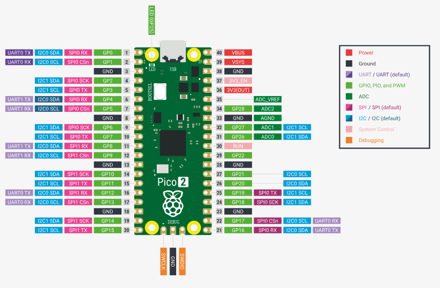
The Sparkfun 8-channel USB Logic Analyzer previously described in this Techforum article was setup as shown in the next picture using these Qwiic cables to monitor the I2C bus using the proper voltage source, PIN6 (SDA), PIN7 (SCL) (I2C Port 0) and PIN 38 (GND) on the Raspberry Pico 2 as shown below,
and the actual setup in evaluation bread board from Digikey,
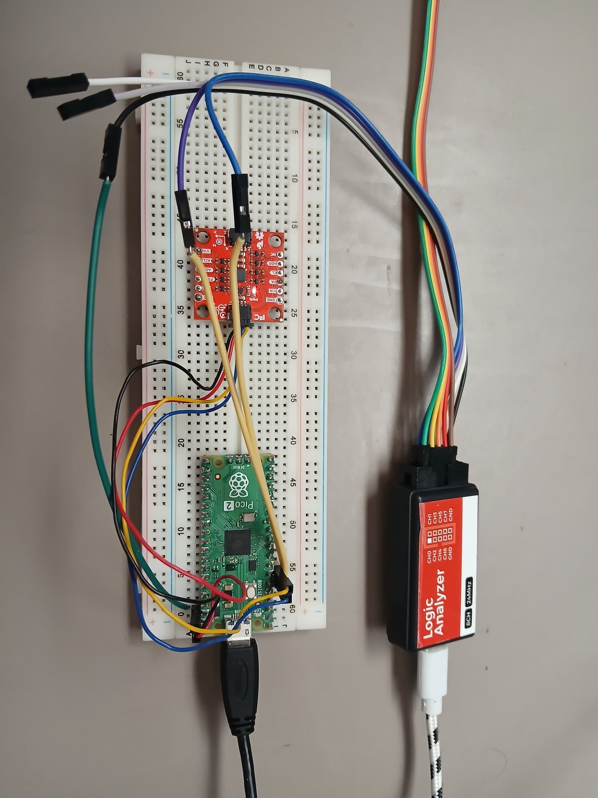
The Sparkfun 8-channel USB Logic Analyzer was connected to the SCL, SDA (I2C bus signals) and the GND (Ground) as shown above (Not the optimum way of connecting it due to long cable runs, increased first order lumped RC time constant, etc, perturbation of the I2C bus). Now proceed to flash the Zephyr OS application into the Raspberry Pico 2
(venv) $ west flash --runner uf2
In the minicom terminal the output will display from the Raspberry Pico 2 the following,
david_digikey_coffee_cup_zephyr_i2c_read(address)
I2C Bus Digikey Coffe Cup Reading Address = 0x00 is 0xEA
I2C Bus Digikey Coffe Cup Reading Address = 0x06 is 0x41
I2C Bus Digikey Coffe Cup Write to Address = 0x06, Register=0x01 Complete
I2C Bus Digikey Coffe Cup Reading Address = 0x06 is 0x01
I2C Bus Digikey Coffe Cup Write to Address = 0x06, Register=0x41 Complete
I2C Bus Digikey Coffe Cup Reading Address = 0x06 is 0x41
The Sparkfun 8-channel USB Logic Analyzer confirms that this Zephyr C program running inside the Raspberry Pico 2 using only the I2C definition in the Zephyr OS overlay works. The proper sequence I2C interface I2C_MSG_WRITE, I2C_MSG_WRITE, I2C_MSG_STOP defined in the main.c developed here at Digikey for the I2C write internal finite state machine is followed. Also the I2C_MSG_WRITE, I2C_MSG_RESTART, I2C_MSG_READ, I2C_MSG_STOP of the I2C read internal finite state machine is followed. The next logic analyzer snapshots, show what is happening inside the I2C bus interface as the Zephyr C program running inside the Raspberry Pico 2 is interacting with the sensor,

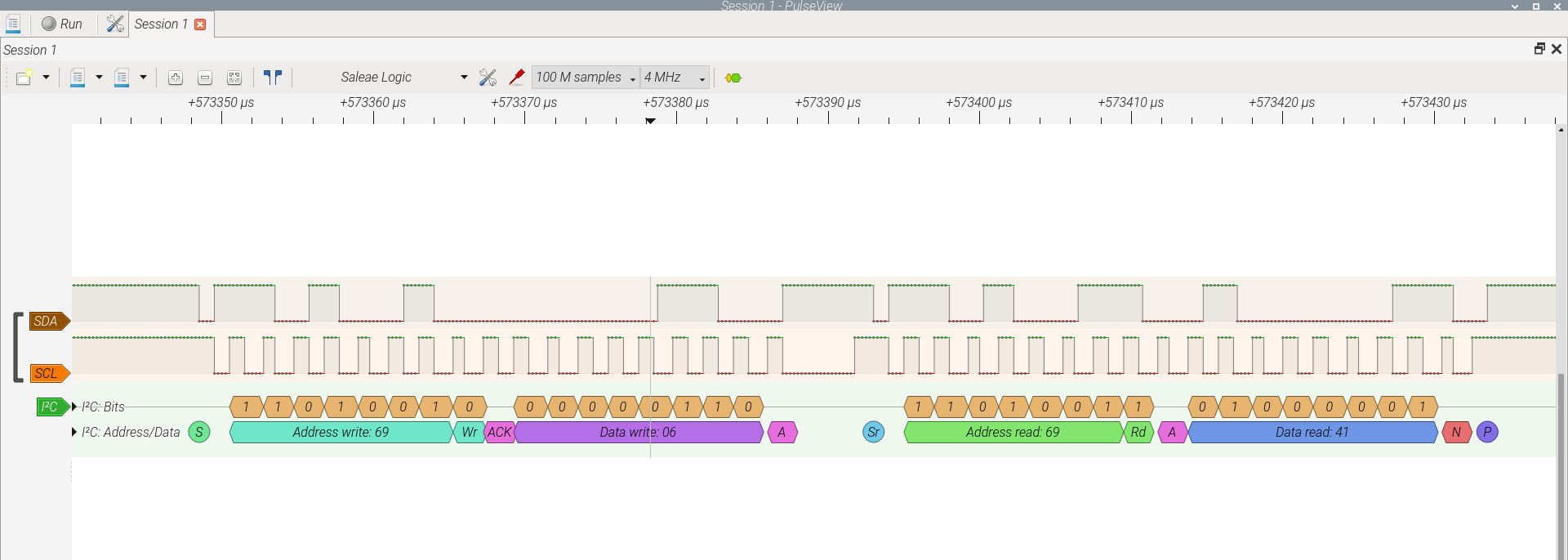

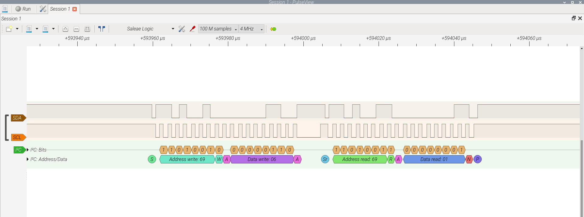


The sequence of proper I2C read/write transactions are confirmed by the logic analyzer on the I2C bus to the slave device. The WHOAMI register is read in the loop, changes to the PWR_MGMT_1 register are performed to place it in awake mode or sleep mode (in sleep mode all analog is powered off).
The Sparkfun 8-channel USB Logic Analyzer available at Digikey, is an excellent tool when there is need to work in these types of interfaces. (CAN bus, SPI bus, I2C bus, among others, where many devices can be analyzed accordingly) Have a nice day!
This article is also available in spanish language here.
Este artículo está disponible en idioma español aquí.