In the previous article it was shown how to connect to the the TDK ICM-20948 Sensor Qwiic Platform Evaluation Expansion Board from Sparkfun to scan the slave I2C addresses of the sensor from the Zephy OS shell. In this article the Zephyr OS build process application, with the essential files and directory structure will be described for the Raspberry Pico 2. First, open a minicom terminal which will be used later to see the output from the Raspberry Pico 2 that will run the Zephyr OS application.
$ minicom -D /dev/ttyACM0

Welcome to minicom 2.8

OPTIONS: I18n
Port /dev/ttyACM0, 12:41:43

Press CTRL-A Z for help on special keys
Within the Zephyr directory create a folder called myproject, then inside that folder create the following files.
The CMake file named CMakeLists.txt,
cmake_minimum_required(VERSION 3.25.1)
find_package(Zephyr REQUIRED HINTS $ENV{ZEPHYR_BASE})
project(i2c_scanner)
target_sources(app PRIVATE src/main.c)
The Zephyr OS configuration file named prj.conf,
CONFIG_I2C=y
The Zephyr OS Overlay file in this case named RP2350.overlay that defines the I2C port in this case i2c port 0 in the Raspberry Pico 2,
/ {
    aliases {
        scan-i2c = &i2c0;
    };
};
The main.c program that will reside in a new subfolder called src.
#include <zephyr/kernel.h>
#include <zephyr/device.h>
#include <zephyr/drivers/i2c.h>
#include <zephyr/sys/printk.h>

#define CONFIG_I2C_SCAN_ADDR_START 0x00
#define CONFIG_I2C_SCAN_ADDR_STOP  0x99

static const struct device *scan_dev = DEVICE_DT_GET(DT_ALIAS(scan_i2c));

int main(void)
{
    k_sleep(K_SECONDS(5));
    if (!scan_dev) {
        printk("I2C: Device driver not found.\n");
        return -1;
    }

    printk("*** Digikey I2C scanner started ***\n");
    printk("Board:           %s\n", CONFIG_BOARD);
    printk("I2C device:      %s\n", scan_dev->name);

    /* Print pin information if available in devicetree */

    if (!device_is_ready(scan_dev)) {
        printk("I2C device not ready\n");
        return -1;
    }

    printk("Digikey Scanning on I2C bus...\n\n");

    printk("    | 0x00 0x01 0x02 0x03 0x04 0x05 0x06 0x07 0x08 0x09 0x0a 0x0b 0x0c 0x0d 0x0e 0x0f |\n");
    printk("****|*********************************************************************************");

    uint8_t error = 0u;
    uint8_t dst;
    uint8_t i2c_dev_cnt = 0;
    struct i2c_msg msgs[1];
    msgs[0].buf = &dst;
    msgs[0].len = 1U;
    msgs[0].flags = I2C_MSG_WRITE | I2C_MSG_STOP;
    uint16_t slave_addr = 0;

    /* Use the full range of I2C address for display purpose */
    for (uint16_t x = 0; x <= 0x7f; x++) {
        /* New line every 0x10 address */
        if (x % 0x10 == 0) {
            printk("|\n0x%02x| ",x);
        }
        /* Range the test with the start and stop value configured in the kconfig */
        if (x >= CONFIG_I2C_SCAN_ADDR_START && x <= CONFIG_I2C_SCAN_ADDR_STOP)	{
            /* Send the address to read from */
            error = i2c_transfer(scan_dev, &msgs[0], 1, x);
                /* I2C device found on current address */
                if (error == 0) {
                    printk("0x%02x ",x);
                    slave_addr = x;
                    ++i2c_dev_cnt;
                }
                else {
                    printk("#### ");
                }
        } else {
            /* Scan value out of range, not scanned */
            printk("     ");
        }
        k_sleep(K_MSEC(15));
    }
    printk("|\n");
    printk("\nI2C device(s) found on the bus by Digikey: %d\nScanning complete!\n\n", i2c_dev_cnt);

}
The complete folder myproject will look like this,
|-- CMakeLists.txt
|-- prj.conf
|-- RP2350.overlay
`-- src
    `-- main.c
Now at this point build the Zephyr OS application for the Raspberry Pico 2 using the previous RP2350.overlay file as follows,
(venv) $ west build -p always -b rpi_pico2/rp2350a/m33 -S cdc-acm-console -- -DCONFIG_USB_DEVICE_INITIALIZE_AT_BOOT=y -DEXTRA_DTC_OVERLAY_FILE=RP2350.overlay
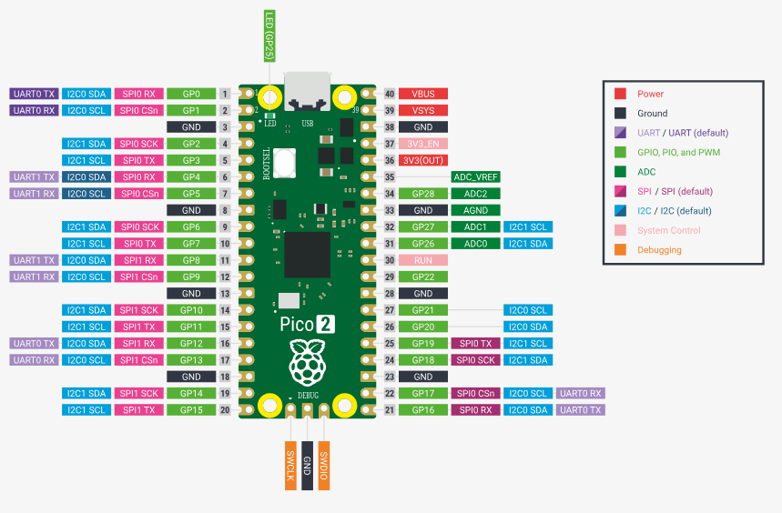
The Sparkfun 8-channel USB Logic Analyzer previously described in this Techforum article was setup as shown in the next picture using these Qwiic cables to monitor the I2C bus using the proper voltage source, PIN6 (SDA), PIN7 (SCL) (I2C Port 0) and PIN 38 (GND) on the Raspberry Pico 2 as shown below,
and the actual setup in evaluation bread board from Digikey,
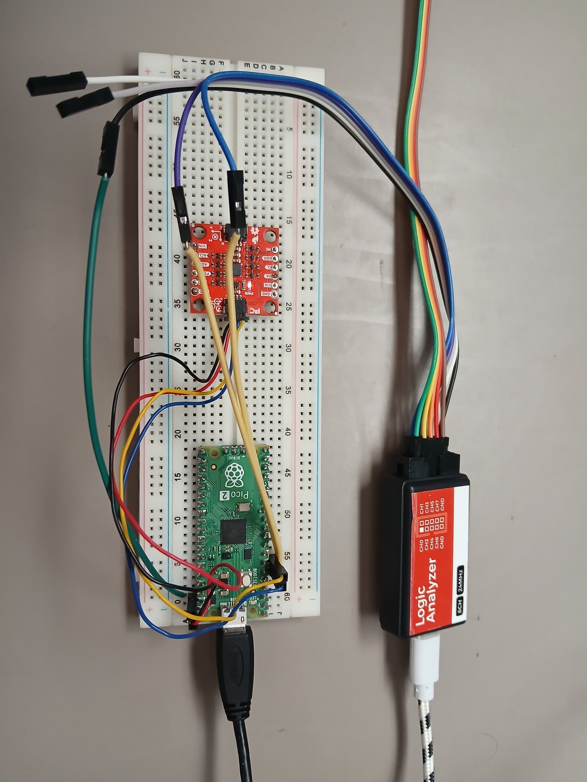
The Sparkfun 8-channel USB Logic Analyzer was connected to the SCL, SDA (I2C bus signals) and the GND (Ground) as shown above (Not the optimum way of connecting it due to long cable runs, increased first order lumped RC time constant, etc, perturbation of the I2C bus). Now proceed to flash the Zephyr OS application into the Raspberry Pico 2
(venv) $ west flash --runner uf2
In the minicom terminal the output will display from the Raspberry Pico 2 the following,
*** Booting Zephyr OS build v4.2.0-5176-ge5838ffc2176 ***
*** Digikey I2C scanner started ***
Board:           rpi_pico2
I2C device:      i2c@40090000
Digikey Scanning on I2C bus...

    | 0x00 0x01 0x02 0x03 0x04 0x05 0x06 0x07 0x08 0x09 0x0a 0x0b 0x0c 0x0d 0x0e 0x0f |
****|*********************************************************************************|
0x00| #### #### #### #### #### #### #### #### #### #### #### #### #### #### #### #### |
0x10| #### #### #### #### #### #### #### #### #### #### #### #### #### #### #### #### |
0x20| #### #### #### #### #### #### #### #### #### #### #### #### #### #### #### #### |
0x30| #### #### #### #### #### #### #### #### #### #### #### #### #### #### #### #### |
0x40| #### #### #### #### #### #### #### #### #### #### #### #### #### #### #### #### |
0x50| #### #### #### #### #### #### #### #### #### #### #### #### #### #### #### #### |
0x60| #### #### #### #### #### #### #### #### #### 0x69 #### #### #### #### #### #### |
0x70| #### #### #### #### #### #### #### #### #### #### #### #### #### #### #### #### |

I2C device(s) found on the bus by Digikey: 1
Scanning complete!
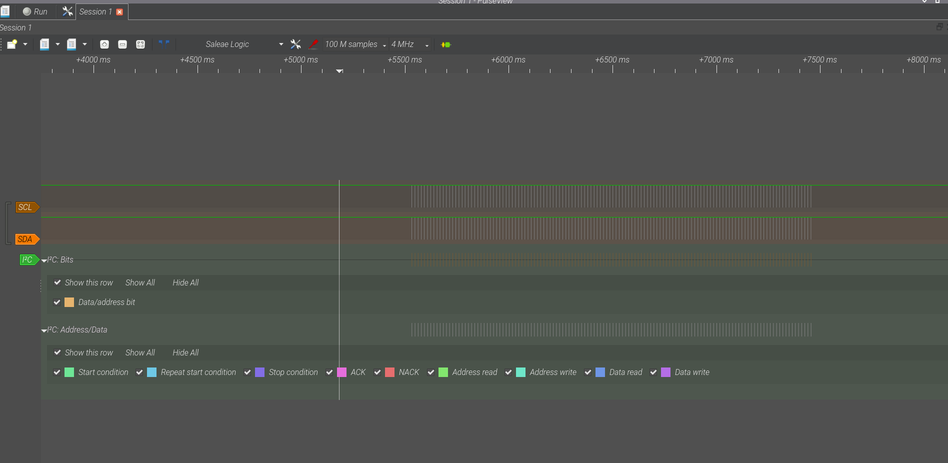
The I2C slave address of 0x69 was properly registered by the Zephyr OS application in the Raspberry Pico 2. Also matching the I2C device: i2c@40090000 used in the previous article. In order to verify this, the Sparkfun 8-channel USB Logic Analyzer was configured to display only 2 channels, setup the collection rate to 4 MHz, 100 million samples, and to use the I2C protocol decoder. The following I2C bus snapshots were captured by the Sparkfun 8-channel USB Logic Analyzer while the Zephyr OS program was reset. The first I2C bus capture shows the whole sequence of I2C address scan performed by the previously described Zephyr OS main.c program
Zooming into a I2C message sent by the Raspberry Pico 2 for the 0x80 I2C slave address scanning case, shows a NACK (In Red below) no Acknowledgement from the I2C slave device,

Finally, to verify the case where the I2C slave device at address 0x69 is detected, it shows the Acknowledgement (Shown in purple below) to the Raspberry Pico 2 running Zephyr OS,

This completes the setup for the Zephyr OS I2C interface using the Raspberry Pico 2 to the TDK ICM-20984 Accelerometer, Gyroscope Sensor Qwiic Platform Evaluation Expansion Board from Sparkfun. Have a nice day!
This article is also available in spanish here.
Este artículo esta disponible en español aquí.