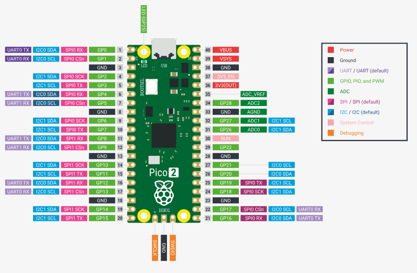
This post illustrates the logic analyzer capturing the I2C transactions that were emitted by the Zephyr OS Raspberry Pico 2 in our previous post. The Sparkfun 8-channel USB Logic Analyzer previously described in this Techforum article was setup as shown in the next picture using these Qwiic cables to monitor the I2C bus using the proper voltage source, PIN6 (SDA), PIN7 (SCL) (I2C Port 0) and PIN 38 (GND) on the Raspberry Pico 2 as shown below,
and the actual setup in evaluation bread board from Digikey,
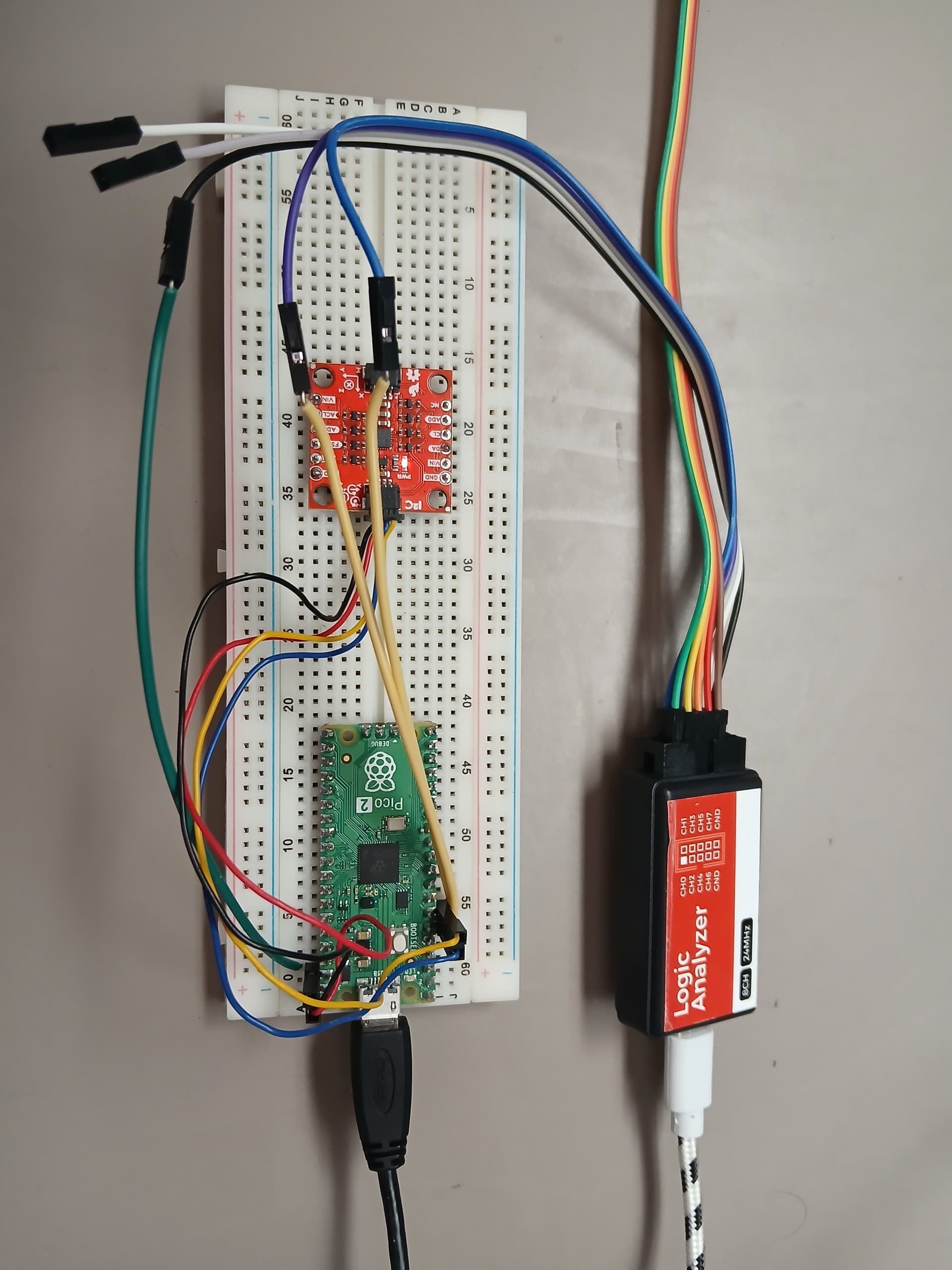
The Sparkfun 8-channel USB Logic Analyzer was connected to the SCL, SDA (I2C bus signals) and the GND (Ground) as shown above (Not the optimum way of connecting it due to long cable runs, increased first order lumped RC time constant, etc, perturbation of the I2C bus). Now proceed to build and flash the Zephyr OS application into the Raspberry Pico 2 (See previous post)
(venv) $ west build -p always -b rpi_pico2/rp2350a/m33 -S cdc-acm-console -- -DCONFIG_USB_DEVICE_INITIALIZE_AT_BOOT=y -DEXTRA_DTC_OVERLAY_FILE=RP2350.overlay
(venv) $ west flash --runner uf2
The ICM-20948 with the I2C slave address is detected properly as 0x69. Now use the I2C interface to read the WHOAMI register of the ICM-20948 as follows,
uart:~$ i2c read_byte i2c@40090000 0x69 0x00
Output: 0xea
The correct value for the ICM-20948 in the Zephyr OS shell running in the Raspberry Pico 2 is received as 0xEA. The output from the logic analyzer is shown below,

In the previous logic analyzer snapshot the read I2C transaction is clearly depicted where the register at address 0x00 is requested from the master I2C device in this case the Raspberry Pico 2 running Zephyr OS to the ASIC inside the ICM-20948 sensor. The received value WHOAMI is 0xEA as shown in the logic analyzer.
Now proceed to read the low power feature inside the ASIC as follows,
[/wrap]
uart:~$ i2c read_byte i2c@40090000 0x69 0x05
Output: 0x40
The default value of operation is in duty cycled mode (Operate I2C master in duty cycled mode. ODR is determined by I2C_MST_ODR_CONFIG register). Now change the low power configuration mode to remove duty cycled mode of the sensors as follows and read it back to confirm the change,
uart:~$ i2c write_byte i2c@40090000 0x69 0x05 0x00
uart:~$ i2c read_byte i2c@40090000 0x69 0x05
Output: 0x0

In the previous logic analyzer snapshot the I2C write transaction is captured that shows the update of address 0x05 to 0x00. The Sparkfun 8-channel USB Logic Analyzer previously described in this [Techforum article]( Zephyr OS en la Raspberry Pico 2 con interfaz I2C al SPARKFUN 9DOF IMU (Linux) Parte 2 - foro en español - DigiKey TechForum - An Electronic Component and Engineering Solution Forum

is a portable, easy to use testing device and is currently available at Digikey. Have a nice day!
This article is also available in spanish here.
Este artículo esta disponible en español aquí.