USB Type-C CC Logic and PHY components

Clarification Needed: USB Type-C CC Logic and PHY components

Hello,

I’m working on a USB Type-C implementation (USB 2.0, no PD) and need clarification on several technical aspects:

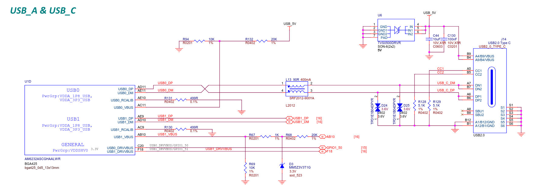
  1. Regarding CC pins and pull-up/pull-down resistors:

    • You’ve mentioned that 5k1 resistors are always required, is that required by the USB-IF
    • Does this resistance value affect the actual current draw or voltage in the UFP once the DFP communicated that it is capable of providing? for example DFP with usb 3.2 gen 1 (USB 3.0) port with PD is capable of providing 100W (20V 5A) does the UFP can say it wants only 15W (5V 3A)?
  2. CC Logic Controller:

    • I see the BD91N01NUX is suggested for handling CC logic. To confirm, this only manages the CC functionality and not the USB PHY, correct? (image and link to source).
    • Does the BD91N01NUX implement the new* specification for billboard?
  3. PHY Implementation:

    • What are the key requirements for the USB 2.0 PHY in a Type-C implementation?
    • How does the PHY interface with the CC logic?

Any clarification would be greatly appreciated, especially regarding the understanding of the CC lgoic and PHY.

Thanks in advance!

Source Page 4

Hi @WilderPumpking76 , what features of Type-C does your design really need? Are you just looking to utilize a Type-C connector and wire up USB 2.0? (allowing either HOST or Peripheral mode?) Or do you want to force a specific wattage?

For reference, here is one design done recently.. Using TI AM6232, where we just wanted USB; so USB 2.0 to Type-C connector:

PocketBeagle 2: pocketbeagle2_sch.pdf · main · PocketBeagle / PocketBeagle 2 · GitLab

Regards,

2 Likes

Hello @RobertCNelson,

Thank you for your replay and reference design.

Mostly my question was to understand TI Primer on USB and the CC logic and PHY components.

I need the basics of type c features i.e. USB 2.0 receptacle with no PD (5V 3A).
However, it was mentioned in the post that wiring up 2 5k1 is not the standard and wont power off (or billboard) when the host is not capable to provide.
Therefore, it was suggested to use a chip like BD91N01NUX when trying to draw more then 0.5A.

In my particular case I want to power using my laptop USB 3.2 gen 1 port (capable of PD) or a USB type c charger (capable of 15W)
To power a PCB with stm32g474 chip that will draw max 1.5A.

Best Regards,
Wilder

Yes, 5.1kΩ (±20%) pulldowns on CC1 and CC2 are required on an UFP to signal that it is an UFP (power sink).

Does this resistance value affect the actual current draw or voltage in the UFP once the DFP communicated that it is capable of providing? for example DFP with usb 3.2 gen 1 (USB 3.0) port with PD is capable of providing 100W (20V 5A) does the UFP can say it wants only 15W (5V 3A)?

No, it only communicates the (initial) role of the port, nothing about power requirements. The only way to have two-way communication about power is using PD signalling, which is also the only way to negotiate a higher voltage than 5V.

Without PD, the UFP merely communicates that it wants power, the DFP communicates (using the strength of its pull-ups) whether you are allowed to draw 3A, 1.5A, or “default USB power” (pre-USB-C rules, more or less). See this comment and this comment for details.

I see the BD91N01NUX is suggested for handling CC logic. To confirm, this only manages the CC functionality and not the USB PHY, correct?

Correct. It simply measures the voltage on the CC lines (with appropriate filtering) and outputs control lines that indicate the status (disconnected/invalid, default USB power available, 1.5A current available, 3A current available) and plug orientation (relevant for USB3).

It is your responsibility to use these control signals to somehow ensure your device’s current draw complies with the requirements.

Does the BD91N01NUX implement the new* specification for billboard?

Not its job, it is not involved in USB2/3 communication at all. Note that implementation of the billboard device class is not required if

  • you use USB-C for power only (no USB phy or USB-C alternate mode), or
  • you can reduce your power consumption to meet the advertised current without significantly affecting device functionality (e.g. a charge port on a battery-powered device).

What are the key requirements for the USB 2.0 PHY in a Type-C implementation?

I’m not aware of it having any key requirements, those are covered by the USB 2.0 specification, not the Type-C specification.

How does the PHY interface with the CC logic?

It doesn’t.

5 Likes

Note that the STM32G474 has a built-in Type-C controller, hence there should be no need for the BD91N01NUX provided that software can limit your device’s power consumption.

2 Likes

ST has a few design tools you should look at for this: https://www.st.com/en/development-tools/stm32cubemonucpd.html

USB: https://wiki.stmicroelectronics.cn/stm32mcu/wiki/Category:USB
USB PD: https://wiki.stmicroelectronics.cn/stm32mcu/wiki/Category:USB_Power_Delivery

Regards,

2 Likes