Hi,
I want to divide a high voltage, for example, 124 V, into 100 V and 24 V. Can you suggest some voltage divider circuit that is rated for high voltages?
Thank you!
Xiaheng
Hi,
I want to divide a high voltage, for example, 124 V, into 100 V and 24 V. Can you suggest some voltage divider circuit that is rated for high voltages?
Thank you!
Xiaheng
The key resistor specification is the “Maximum Working Voltage” listed in the part data sheet. For a 120V or higher circuit you should use resistors rated for 250V or higher to provide a good safety margin.
All through hole mount standard resistors I’ve encountered have a rating of 250V or higher (physically larger usually = higher voltage). For surface mount resistors you typically need a very large size to get a working voltage of 250.
There are an infinite number of resistance pairs that will divide to a specific voltage ratio. There are usually only hundreds of available resistor values that can divide close enough to the desired voltage. All resistors also have a resistance tolerance so combined with limited values you need to provide a specification for the accuracy of the output voltages so that values can be calculated.
You need to specify another key parameter for a voltage divider circuit to narrow down the choices, the maximum allowed current draw of the voltage divider. A higher permissible current draw allows for lower resistance value pairs.
Another important factor is the impedance of the circuit that uses the output of the voltage divider, the load impedance.
If it’s a high impedance like a multi-meter there is only a tiny impact on the divider calculation and the load impedance can usually be ignored. If the impedance of the load is low like an incandescent light bulb, there will be a major impact on the calculation.
If the load impedance varies during operation it needs to be either, tiny so it can be ignored or, isolated from the divider by an active circuit. Otherwise the output voltage will vary significantly as the load impedance changes.
Finally, keep in mind that voltages above 50V are safety hazards. Improper calculations or construction can lead to shock and fire hazards.
Hi Paul,
Thanks for your informative answer - which let me realize that I have the load impedance matching issue.
So my load is supposed to get 100 V, but the load resistance will change from very high (~Mohm) to 100 ohm when the voltage (100V) is supplied to it, at that time, the overall resistance becomes so low so the voltage dividing is messed up.
Do you think there is a way to work around such issue?
Thank!
You need to use an active voltage regulator circuit rather than a passive voltage divider circuit.
This is the exact problem voltage regulators where originally invented to solve a hundred years ago (the first practical versions where electro-mechanical).
Unfortunately I don’t think there are any off the shelf, 124V input, 100V output, regulator IC’s or modules, so this requires a custom engineered circuit.
Hi Paul,
Thanks for the reply. Yeah, I also realize this must be an issue low time back.
For the custom engineered circuit, I am not specialized in this, is there a way that I can get help from Digikey? Or can you recommend some outsourced vendors that can help with the design?
Thanks!
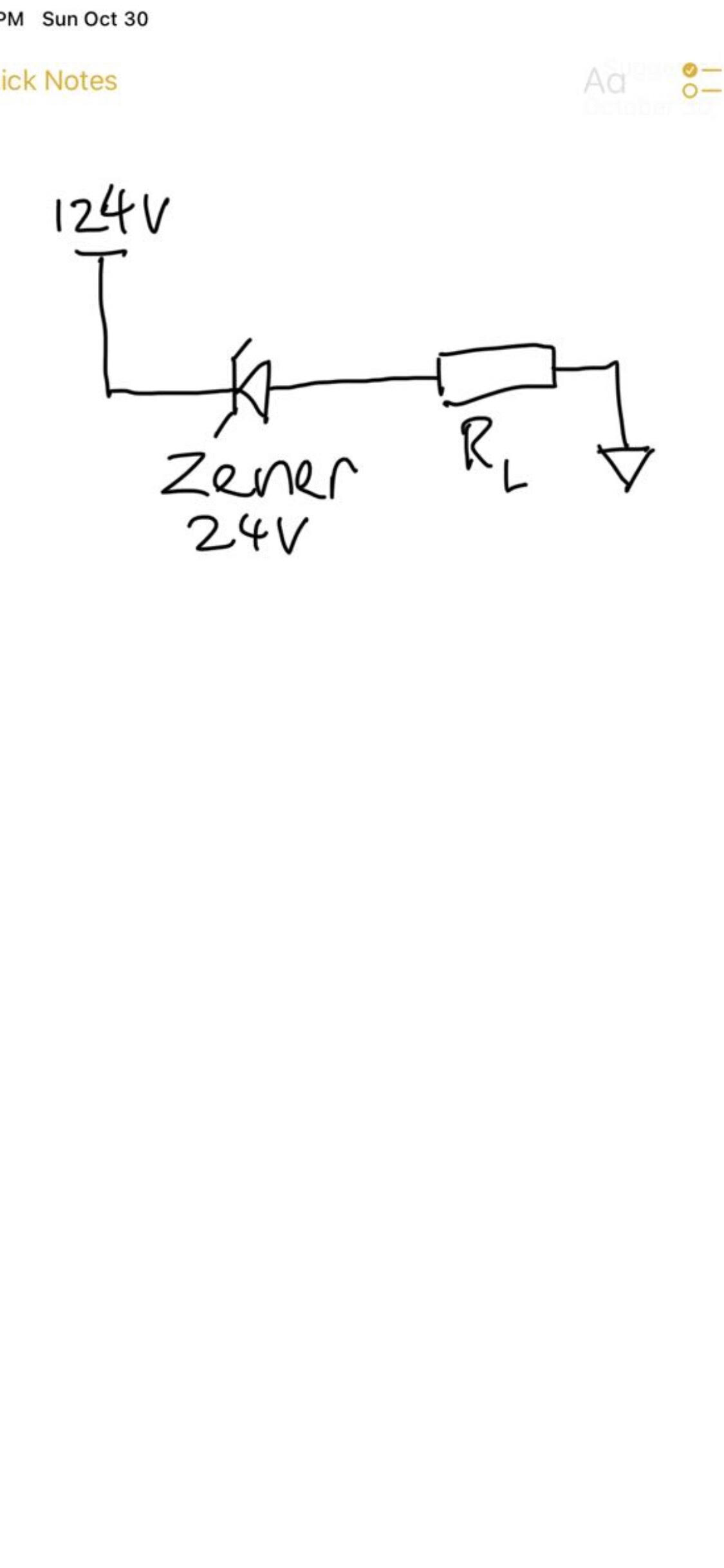
To reiterate the problem -
In the circuit drawn here, I have a load resistor (R_L) that becomes 100 ohms when it is loaded with a large voltage bias (~100 V). This R_L is considered very large compared to R2 when the voltage dropped on it is low (e.g, 10 V). The challenge is to regulate the voltage between R2 (and R_L) to be constantly at ~100 V, and in the mean time, the voltage between R1 can also maintained around 24V.
I’m just a forum member and don’t currently have free time to help with the design. I’m sure somebody from Digi-Key will let you know what help they can offer.
Are they going to reply on this thread or should I pin someone? I am new to this Forum
They’ll reply in the thread
Paul,
Actually, here is a try (credit from my friend) -
The idea is to not regulate the load (hence R2), but to regulate the R1 using a zener diode. Do you think this is fair? (it is a very simple design!)
Thanks!
If the zener has high enough power handling capability it can work as long as you only need the output will be Vin - 24V.
You may need a heat sink on the zener to dissipate the 24 Watts and not end up with thermal runaway.
Thank you for the additional comments! I will look up a couple of P/Ns.
This part should do the trick.
Thanks! This is very helpful.
Hi Paul,
A follow-up question - just curious why this Zener diode’s connection looks so different than a typical through hole or SMD diodes? Is it due to the fact that this is rated high power? If so, why this connection is better? Please advise.
Thanks!
Yes, it’s for the power and because it will often need to be bolted to a large metal heat sink.
Hi Paul,
Gotcha. Do you mind give more tips on what kind of heat sinks should I purchase along with this part? And proper connectors?
Or I can start a new thread asking for such. I am new to this kind of conneciton.
I don’t think there are any stock heatsinks for chassis mount zener diodes.
Normally they are just bolted to a metal chassis and the thermal mass of the chassis is the heat sink.
In this situation calculating the amount and shape of the metal for a heatsink is far more time consuming than simply experimenting. Normally I’d say mount it in a convenient low cost method, turn it on, and feel the zener’s temperature to make sure it doesn’t get too hot. If it get’s too hot then use more metal, metal shaped for better heat transfer via convection, or add forced air flow across the sink area.
However in your situation the heat removal connection is also dangerous high voltage DC at a high enough current to potentially kill almost any human being. So you’ll need a thermometer that can be attached to a live high voltage surface so you can read the temperature.
For the final application you’ll need to design a system where nothing can come in contact with the metal used to sink the heat while convection can still transport the heat away from the metal.
There are dozens to hundreds viable methods of solving almost any electronics engineering problem. With voltage regulation there are many choices, and load only regulation via a series connected zener is almost, maybe always, never a good solution. In the 21st century zeners for high power regulation are usually higher in cost than other methods, and in this case also a fire and shock hazard.
Tell us what the actual application is and I’m almost certain somebody on the forum can think of a lower cost and safer alternative to using a series connected zener diode.
Hi xiaheng,
Paul has given a lot of good advice. His warnings are particularly important to heed.
If we want to find a workable solution, it’s important that we clearly understand your scenario and understand what your goals are. So, a few questions:
Can you describe your overall application? (More than just “I have this voltage and need to get that voltage”. The more you can tell us about it, the more likely that we can come up with a viable and reasonable solution. So, including things like what the device is and what it is used for, what sort of environment (indoor, outdoor, high/low temperatures, moisture of environment, etc.) in which it will be operating, physical size and mounting, could all be helpful.)
Regarding your 124V source:
Regarding your load:
Hi Paul and David,
I am glad that you can provide such a lot of information! Let me be crystal clear from now on (I will do my best!).
Here is my detailed description with an image, I also did some naive calculations so you can help me check if things look reasonable or not. I am not familiar with circuits, so bear with me (eager to learn as well!).
The main target is to provide two regulated voltages to two different loads.
(1) One load has a large resistance (Gohm maybe). It is supposed to be regulated at 24V.
(2) The 2nd load is a PN junction, and I need to reverse bias it to its breakdown voltage (-35V) (this is not an off-shelf PN junction, I microfabricated it inside a cleanroom at my university). During breakdown, the load resistance of this PN junction is Rload = 300 ohm. R1 is the additional resistor that is paralleled with Rload.
The PN junction devices are microchips, so I plan to mount them onto PCB boards with wire bonding. And using the wires out for connection to the external circuit that I am designing here. And it is just going to be lab ambient condition for operation so no worry on those.
DC source -
I will use a Keithley sourcemeter 2400 to provide the DC voltage. I was making up number like 124V. In reality, it is going to be 24V + a voltage larger the breakdown voltage of the PN junction, say 50 V as the example here. So the total Vin will be equal to 74V.
I am not sure about the internal output impedance, please advise if it matters if I used a sourcemeter here.
PN junction (breakdown at -35 V) load and pick of the Zener diode
I already mentioned that this load has a “dynamic load”, before breaks down, the load is very high, and during breakdonw, it is 300 ohm. And this is why this problem becomes interesting - what the value of R1 should be?
See some calculations I did below -
The current running through the load during the breakdown is assumed to be 50/300 = 0.16 A. So I picked up a 10W rated zener diode that has a test current of 0.105 A at the regulated 24V. And based on this, to initiate the regulation of the Zener itself at the beginning (without breakdown the load PN junction yet), I concluded that the max of R1 needs to be below 50/0.105 = 476 ohm. Then, since the max DC current allowed is 0.35 A for the Zener, during the breakdown of the PN junction load, the combined resistance of the load with R1, R_//, should be larger than 50/0.35 = 143 ohm, and that gives a lower bound of the R1 =272 ohm. So the R1 should be between 272 to 476 ohm if I operate the breakdown mode of the PN junction load at 50 V. Then if I choose a R1 = 350 ohm, the power rating needs to be 50^2/350 = 7 W at least.
Does my logic above make sense?
If so, I put one step forward, if I operate the PN junction at an even larger breakdown voltage, the min and max of R1 can be calculated, and as you can see in the table, the range of the resistor value becomes smaller and smaller and it is no longer valid beyond 70V.
I hope I have explained myself enough.
The final thought is that the circuit I am proposing here is just a thought, it might be a better way to do this. If so, please enlighten me. Thanks!
Let’s start from here.