Summary
This article provides a brief introduction to the door interlock commonly used for machine guarding in an industrial environment. From an electrical perspective, the door interlock is closely related to an E-stop. Both contain normally closed switch contacts that are monitored by a safety relay or a safety-rated Programmable Logic Controller (PLC).
![]() Estimated reading time: 4 minutes
Estimated reading time: 4 minutes
![]() This article is part of DigiKey’s Siemens PLC and Automation Resource Hub. Visit the hub for more technical briefs on Siemens components, applications, and programming.
This article is part of DigiKey’s Siemens PLC and Automation Resource Hub. Visit the hub for more technical briefs on Siemens components, applications, and programming.
Introduction to Mechanical Door Interlocks
Is machine guarding more important than machine control?
The ideal machine is fully guarded with zero chance of personnel coming into contact with hazards. There are no exposed pinch points, exposure to electrical, or exposure to a hazardous process. This ideal is compromised when we consider maintenance and the need to load material into the machine. In those cases, it is imperative to properly guard the machine openings.
In this engineering brief, we explore the Siemens 3SE52320QV40 and the associated 3SE50000AV01 die-cast key, as shown in Figure 1. When properly installed, this switch may be used to monitor the status of a door. According to this Siemens document, the switch may provide protection ranging from Safety Integrity Level 1 / Performance Level c (SIL 1 / PL c) up to SIL 3 / PL e with the understanding that the switch alone can be rated no higher than SIL 2 / PL d.
Safety: Consult a safety engineer to evaluate your application. By my understanding of safety, there are many ways to break integrity. These unintended failures may not be immediately obvious.
Note that SIL and PL qualify the hazard associated with a machine or process. SIL identifies increasing levels of danger from SIL 1 to SIL 3 in accordance with IEC 62061. With qualifications, the same ideas are reflected in PL a up to PL e according to ISO 13849-1.
Ref: IEC: https://webstore.iec.ch/en/publication/59927
Ref: ISO: ISO 13849-1:2023 - Safety of machinery — Safety-related parts of control systems — Part 1: General principles for design
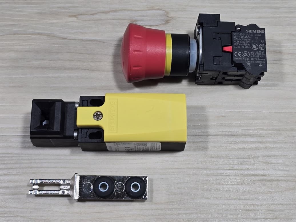
Figure 1: A Siemens E-stop switch (top) shown with a door monitoring switch with separate actuator (middle/bottom).
Redundancy for High SIL/PL Ratings
Novice designers will be tempted to wire operators such as E-stops and door interlocks directly to a standard PLC. This is a bad (unsafe) idea as:
-
Standard PLCs are not rated for safety.
-
There is little to no intrinsic safety.
-
There is little to no redundancy.
Instead, devices such as E-stops and door interlocks should be monitored by safety relay or safety-rated PLC.
Safety Attributes of an Industrial Door Interlock
Tamper Resistance
The door interlock has a matching key (close-up image in Figure 2). This prevents the operator, or more likely, a technician from defeating the mechanism. However, this is not 100% safe as a clever and dedicated technician may “pick” the mechanism or simply pull another key from stock.
Tech Tip: Consider adding an RFID-based safety interlock for door detection. An example is the Siemens 3SE63 series.
While nothing is completely tamper-resistant, the RFID is harder to defeat than a mechanical switch. There may also be a safety benefit from using multiple switches where different technologies are incorporated. Consult a qualified safety engineer.
What to Ask Yourself:
What would you do if a technician bypassed the interlock in the control panel?
Why would an RFID interlock be safer than a mechanical interlock?
Why would multiple interlocks with different technologies be safer?
Electrical Attributes
The featured Siemens door interlock has two Normally Closed (NC) and a single Normally Open (NO) contacts. We can understand the door interlock by comparing it to an E-stop switch which also has two NC contacts. In both cases, we wire the safety devices to a safety relay:
-
Two wires are used for redundancy.
-
NC contacts are used to provide a fault. This configuration also detects broken wires.
-
The safety module provides a signal to and monitors the response from each contact. This greatly increases the reliability as short and open circuits may be detected. This includes shorts to 24 VDC, return, and even a short circuit between the safety module’s excitation and return wires.
Next Steps
For additional information about safety relays, refer to this article. There, you will find a demonstration circuit and schematic.
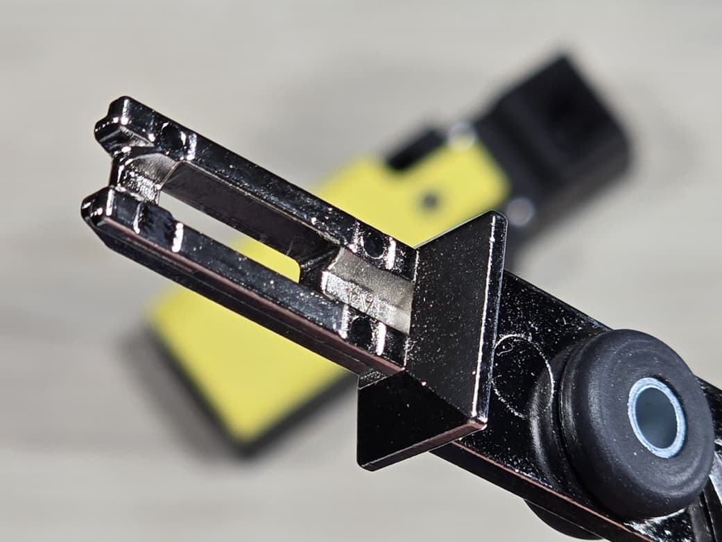
Figure 2: Close-up image of the external actuator showing the key-like tamper-resistant slots.
Parting Thoughts
Be sure to review this Siemens safety document. It’s the type of document you should read often. I learn something new every time I look at it.
Do you have other safety resources? If yes, please add links in the comments section.
Best wishes,
APDahlen
Related Articles by this Author
If you enjoyed this article, you may also find these related articles helpful:
-
Engineering Guide for Light Curtains: Overview and Applications
-
What is OSSD and why is it essential to industrial control safety?
About This Author
Aaron Dahlen, LCDR USCG (Ret.), serves as an application engineer at DigiKey. He has a unique electronics and automation foundation built over a 27-year military career as a technician and engineer which was further enhanced by 12 years of teaching (interwoven). With an MSEE degree from Minnesota State University, Mankato, Dahlen has taught in an ABET-accredited EE program, served as the program coordinator for an EET program, and taught component-level repair to military electronics technicians.
Dahlen has returned to his Northern Minnesota home, completing a decades-long journey that began as a search for capacitors. Read his story here.