Article summary
The Output Signal Switching Device (OSSD) is a safety signaling method commonly used in industrial settings. It features a pair of wires with out-of-phase pulsed signals. The equipment will be shut down if anomalies are detected in the OSSD signal pair.
This engineering brief presents the OSSD waveforms as viewed on an oscilloscope and then briefly explores safety relay and PLC integration issues.
![]() Estimated reading time: 4 minutes
Estimated reading time: 4 minutes
Definition of OSSD
Output signal switching device (OSSD) has two definitions:
-
OSSD describes an industrial safety device such as a light curtain that outputs its safety status on a pair of fail-safe OSSD wires. This definition extends to monitoring devices such as OSSD-equipped safety relays or Programmable Logic Controller (PLC) safety modules.
-
OSSD is a safety protocol implemented at the physical layer with an emphasis on redundancy and protection against common wiring faults such as shorts, opens, or crossed wires. This fail-safe delivery method is used to transfer the state (safe or unsafe) from a safety-compliant sensor to a safety-compliant control module.
Personally, I prefer the protocol definition, as it frames the safety argument in a tangible way. It satisfies my inner-engineer with real signals that can be measured using an oscilloscope.
Demonstration showing the attributes of the OSSD signal
Figure 1 presents the waveform from a SICK deTec4 core light curtain as measured using a Digilent ADP2230 oscilloscope. We are looking at the heartbeat of the OSSD signal generated from an unbroken (machine-safe) light curtain.
The oscilloscope connection is very simple as channel 1 is connected to OSSD1 and channel 2 is connected to the OSSD2 signal. The probe grounds were connected to the DC return line. Finally, a bench power supply was used to power the system, with the DC return connected to earth ground.
Machine safe waveform
From the oscilloscope screen capture, we observe:
- Safety is encoded into two signals called OSSD1 and OSSD2
- Each signal is active high at 24 VDC with periodic dips to 0 VDC
- Each signal periodically dips low at an approximate rate of once every 200 ms
- The signals are out of phase; the OSSD heartbeat has a period of approximately 100 ms
Machine unsafe (broken beam) waveform
If the light curtain beam is broken, both OSSD signals will be at 0 VDC (emphasis on both).

Figure 1: OSSD signal from a SICK light curtain as measured with a Digilent oscilloscope: OSSD1 orange and OSSD2 blue.
Why is the OSSD signal fault tolerant?
Redundancy is a core tenet for industrial safety devices. This is also true for the OSSD signals. The independent wires significantly improve the time-to-failure safety metrics.
The pulsed signals are critical for safety
The safety factor is further improved when we consider the pulsed nature. Now, provided we have a matching safety module with dedicated OSSD inputs, the system is protected against:
- Short to 24 VDC in either wire
- Short to return (ground) in either wire
- Short between OSSD1 and OSSD2
- Open in either wire
- Loss of drive signal from either OSSD signal (e.g. light curtain failure)
- Loss of the safety module’s input circuitry for either OSSD signal
For every listed fault condition, the out of phase pulsed waveform is corrupted. In some cases, only one signal will be impacted (e.g., OSSD1 short to 24 VDC) while in others, both signals will be impacted (e.g., OSSD1 shorted to OSSD2). In all cases, the certified safety relay or PLC module will detect the anomaly and respond by issuing an equipment shutdown.
How is the OSSD a fail-safe system
In this application, the term fail-safe implies that any waveform corruption is interpreted as a non-safe condition and the equipment is shut down. Therefore, equipment failures or wiring errors are handled the same way as when a person or object passes through the monitored light curtain.
We also recognize that the associated OSSD safety relays and PLC safety modules are built with proper attention to redundancy with proper actions for failure mode.
Is OSSD brand specific?
The standardized OSSD signal allows the designer to select compatible building blocks to best suit their application. As an example, consider the Schneider Electric XPSBAT12A1AC safety module. Standardization may allow the SICK light curtain shown in Figure 1 to be used with the safety module shown in Figure 2 (see subsection below).
From the Schneider datasheet we see these specifications:
- Input compatibility: OSSD pair IEC 61496-1-2
- Safety level: Can reach PL e/category 4 for normally open relay contact ISO 13849-1
- Safety reliability data: MTTFd > 30 years ISO 13849-1
DigiKey offers many additional safety modules and PLC safety modules from trusted manufacturers. This flexibility is beneficial when we consider the long service life of industrial equipment or the occasional supply chain disruptions.
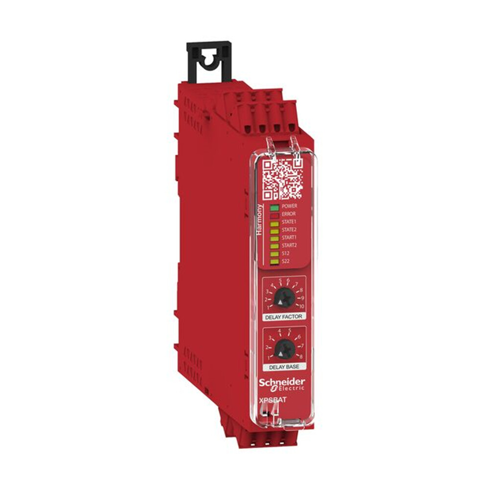
Figure 2: Image of the Schneider Electric XPSBAT12A1AC (Harmony) safety module featuring OSSD inputs.
Do all OSSD signals share the waveform and timing characteristics?
While the general idea appears universal, experiments suggest the timing varies between manufacturer and possibly across product lines. For example, the SICK signal (Figure 1) contains two signals offset in phase with a 100 ms signal event. However, a Banner Engineering SLPR14-270 light curtain as shown in Figure 2 has near simultaneous pulses with a 20 ms repetition period.
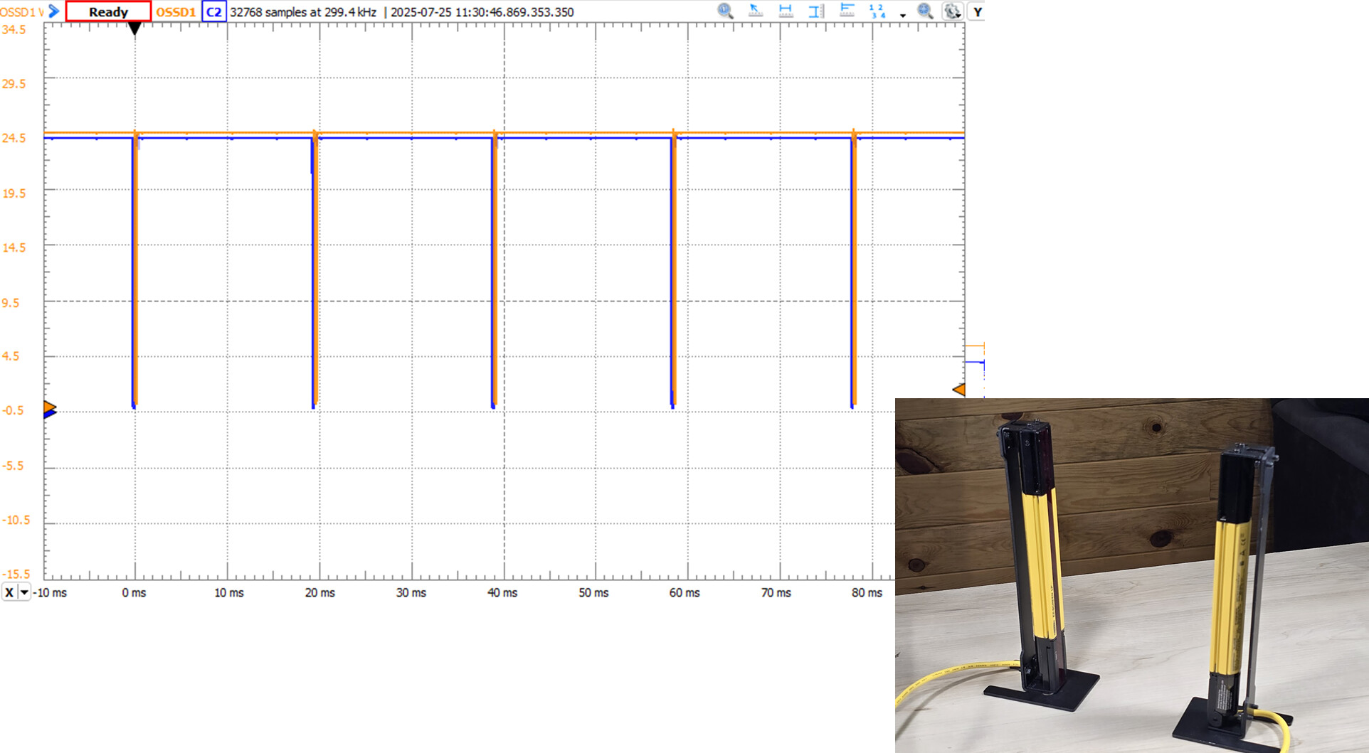
Figure 3: OSSD waveform for a Banner SLPR14-270 light curtain.
Precaution against mixing OSSD products and brands
![]() The fact that the OSSD waveform differs between products and manufacturers opens the potential for non-compatibility. We therefore default to a conservative position for continued safety and compliance:
The fact that the OSSD waveform differs between products and manufacturers opens the potential for non-compatibility. We therefore default to a conservative position for continued safety and compliance:
- Following the manufacturer’s system-level integration recommendations.
- Differ to a qualified safety engineer to select and integrate equipment to the appropriate SIL/PL level.
What type of interface is used for the OSSD signals?
The nature and speed of the signal change as seen in Figure 1 suggests that the light curtain uses PNP semiconductor outputs (no relays clicking). This is a common interface used for 24 VDC sensors in a PLC-dominated industrial environment as described in this engineering brief.
Can the OSSD signal be connected directly to a PLC?
No.
Never connect the OSSD signals directly to a standard PLC. Such a connection bypasses all Safety Integrity Level (SIL) or Performance Level (PL) requirements.
The traditional PLC inputs are not safety-rated and will not detect anomalies in the pulsed OSSD signals. This warning also applies to safety PLCs, as the native I/O pins may not be designed to process the OSSD signal. Instead, use safety-rated PLC modules or, depending on your needs, an independent safety relay.
Adherence to safety standards
Remember that the use of safety equipment does not make the system safe. Instead, the equipment must be properly selected, integrated, installed, and programmed to meet the required safety threshold. Always consult a qualified safety engineer as you design equipment to meet the appropriate hazard level of your system.
Safety note: DO NOT bypass OSSD safety and wire signals directly to a PLC and then use ladder logic to “solve” the problem. Such action is a violation of established safety rules and may carry ethical or legal consequences.
As a sobering reminder, I recently read about the death of a worker caused by the inadvertent activation of an industrial machine. It’s a reminder of our duty to identify and mitigate hazards with proper SIL/PL design and an unyielding adherence to lockout/tagout (LOTO).
Parting thoughts
Safety demands attention to detail.
Safety is a function of equipment selection, integration, programming, and vigilance over the lifetime of your equipment. Knowing the inner workings of the OSSD signal will help you select appropriate equipment. You’ll intuitively think in terms of out-of-phase pulsed signals. You can also see the trap of connecting a light curtain directly to a traditional PLC.
Please add your thoughts and suggestions in the comments section. Let us know if something is missing or if we should add emphasis to aspects of safety.
Best wishes,
APDahlen
Related articles by this author
If you enjoyed this article, you may also find these related articles helpful:
- Introduction to the Industrial Safety Relay
- Engineering Guide for Light Curtains: Overview and Applications
- Color Blindness Accommodations in Industrial Controls
TL;DR
- OSSD (Output Signal Switching Device) provides a standardized way to communicate the safe or unsafe status between a sensor such as a light curtain and a safety module.
- Two signaling wires are used. Each carries a pulsed signal, but the pulses are out of phase. This allows detection of shorts, opens, and other wiring errors.
- The OSSD is an integral part of a fail-safe system. Equipment and wire errors are interpreted as faults causing an immediate equipment shutdown (e.g., loss of a single OSSD signal is interpreted as a fault).
- System integrity demands proper selection, integration, and programming of OSSD equipment.
- Never directly connect the OSSD signals to a standard PLC, as system safety integrity is compromised.
About This Author
Aaron Dahlen, LCDR USCG (Ret.), serves as an application engineer at DigiKey. He has a unique electronics and automation foundation built over a 27-year military career as a technician and engineer which was further enhanced by 12 years of teaching (interwoven). With an MSEE degree from Minnesota State University, Mankato, Dahlen has taught in an ABET-accredited EE program, served as the program coordinator for an EET program, and taught component-level repair to military electronics technicians.
Dahlen has returned to his Northern Minnesota home, completing a decades-long journey that began as a search for capacitors. Read his story here.