Created by Steph Vedvei, last modified by Scott Schmit on Jan 28, 2014
note: This post for reference only. Xbee modules used in project are obsolete and no longer available. It is recommended customers look at the Xbee 3 family from Digi.
Introduction
XBee wireless transceivers provide a quick, easy way to add wireless communication to any system. This page will outline how to set up two XBee Pro Series 2 transceivers for communication with each other.
Hardware
| Quantity | Description | Digi-Key Part Number |
|---|---|---|
| 2 | XBee Pro S2 Transceiver | 602-1181-ND |
| 2 | UART to USB adapter board | 32400-ND |
| 1 | USB cord | Q362-ND |
Step 1: Download X-CTU Software
The X-CTU software is free to download and provides a simple interface to configure and update your XBee transceivers. With this software firmware updates are a breeze and configuration is simple. The software can be downloaded from Digi’s website found here.
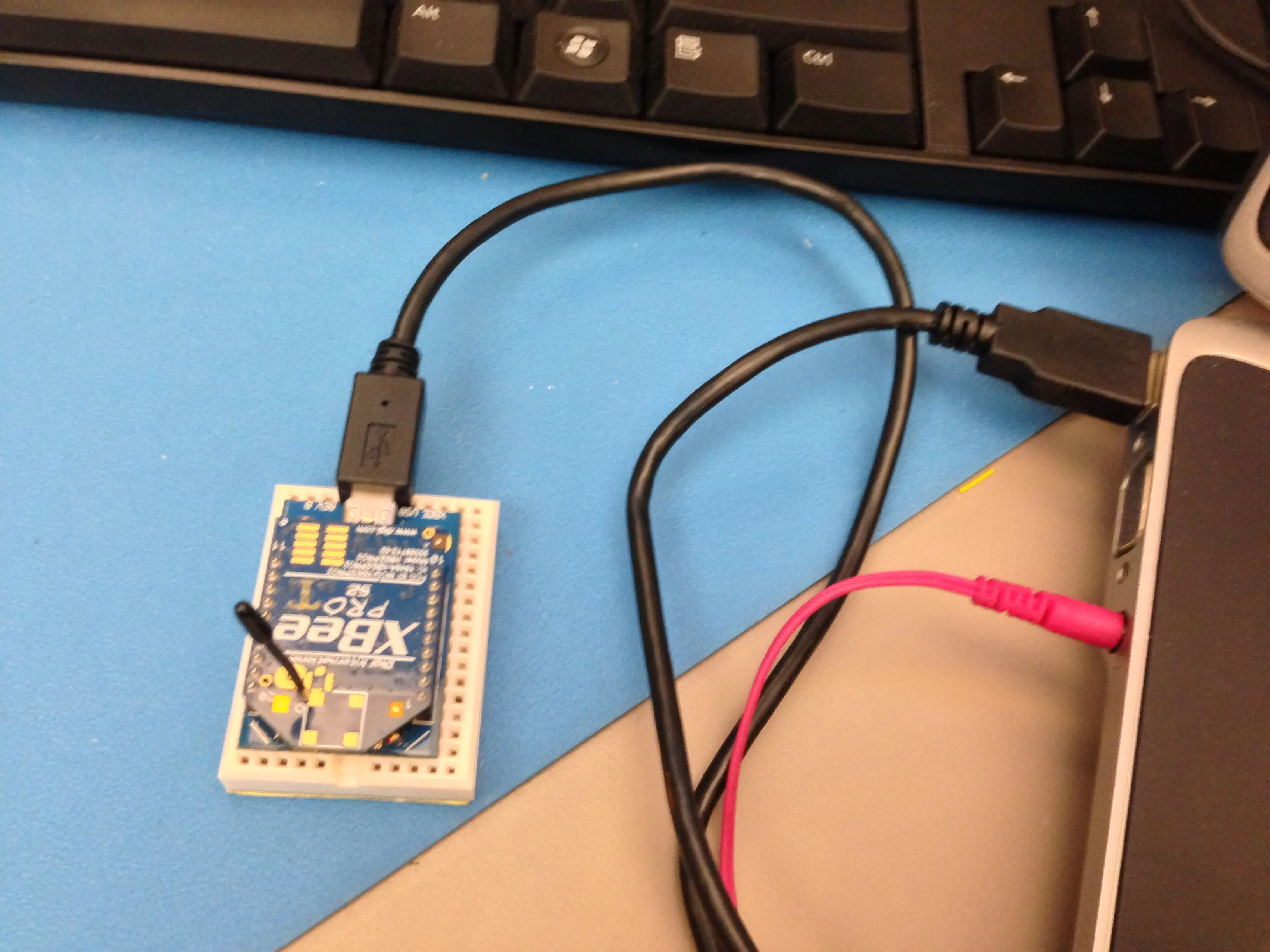
Step 2: Put together your XBee breakout board
The XBee transceivers have a 2mm pin spacing which does not allow them to be plugged into a standard 0.1 inch breadboard. There are, however, several different breakout boards available that allow the transceiver to be inserted into a breadboard. The various adapter boards also allow for connection through USB or serial to your computer. The breakout board used here has a UART to USB conversion circuit and allows the XBee to be connected to the computer and X-CTU software easily. By following the link above in the Hardware list, the data sheet with step by step instructions for putting together the adapter board can be found. After your adapter board is assembled you can plug your XBee into it and then connect it to your computer.
Step 3: Configure 1st XBee as a coordinator
When opening the X-CTU software you should see a window like that shown. After selecting the proper COM port click the Test/Query button.

After selecting the Test/Query button, you should see a dialogue box like the one below. You will want to record the serial number shown as you will need it in a couple minutes.

After recording the serial number you can click OK. Next, select the Modem Configuration tab at the top of the window. Once here, select the read button. This will bring up the current configuration for the connected XBee and will be similar to the following:

Once here, you want to select Zigbee Coordinator AT in the function set drop down menu.

After selecting the coordinator function set, you will need to set the PAN ID. This can be any four digit number and allows the XBees to distinguish between modules in their network and those from other networks. Once you have added the wanted PAN ID click the “Write” button. This will update and configure the XBee. Once this is done you can disconnect the XBee and plug in the second XBee.

Step 4: Configure 2nd XBee as Router
To configure the 2nd XBee, you will follow the same process as for the coordinator with one difference. In the PC settings tab, again, click the “Test/Query” button and record the serial number. Then in the Modem configuration tab, click the read button to load the current configuration of the XBee and set the PAN ID to the same ID used for the coordinator. The only change will be the function set you choose. For the second XBee we will set this as Zigbee Router AT.

After setting the PAN ID and the function set for the router you will put the recorded serial numbers to use. Enter the first 6 digits of the coordinators serial number into the Destination Address High field and the rest of the serial number into the Destination Address Low field. Then select the “Write” button to update the configuration settings for the router. Once this is done updating you can disconnect the router and reconnect the coordinator to the computer.

After re-connecting the coordinator to the computer. You will again go into the Modem Configuration tab and click the read button. You will then want to set the Destination Address to the serial number of the Router XBee in the same manner as you just did for the Router. Once done you will again click the write button to update the coordinator XBee settings. After the write process is complete you are ready to use your XBees and communicate wirelessly!
Step 5: Test the configuration
A simple test can be done to be sure the two XBees are communicating properly. You can connect either one of the XBees to the computer. Then, connect the second XBee to 3.3V power and connect the Dout and Din pins together. This will cause the XBee to automatically retransmit any data it receives.

When you have both XBees connected go to the Terminal tab in the X-CTU window. Whatever you type in the terminal window will appear in blue font and whatever is received will appear in red font. If the XBees are configured correctly every character you type should be mirrored in red.

When typing single characters, you should see a screen similar to the one above. To send strings of data you can assemble a data packet. To do this click the “Assemble Packet” button and type the wanted string into the box then click send data. This will send the entire packet before receiving the same packet back.

If everything you type is being reflected back in red, you are successfully transmitting and receiving with your XBees!! You are now ready to use them however you wish. You can connect them to any microcontroller and transmit data through the UART peripheral or you can connect each XBee to a different computer and have a chat application. There are many more possibilities that are now at your fingertips with your working XBees.
More Useful Information
You can find more information on XBees and setting up larger networks on Digi’s website. Also, here you can find a very useful datasheet for the XBee and XBee-Pro modules. With a general understanding of how to configure your XBee modules and the information in the linked PDF you should now be able to set up any network needed.
We used the XBee modules here to send coordinates to Walt, our heat tracking robot.
XBee Example Usage
- Click here for an example of XBee AT mode using a host microcontroller.
-
Click here for an example of XBee API mode using a host microcontroller.