Hello, I am trying to add the Adafruit RFM95 Lora Radio 1528-1667-ND to my pcb design. I am having a hard time finding dimensions for the positions of the headers to connect it to my pcb. What size of headers should I put on my pcb and where do they need to be placed? thanks!
Hello @jcollins82,
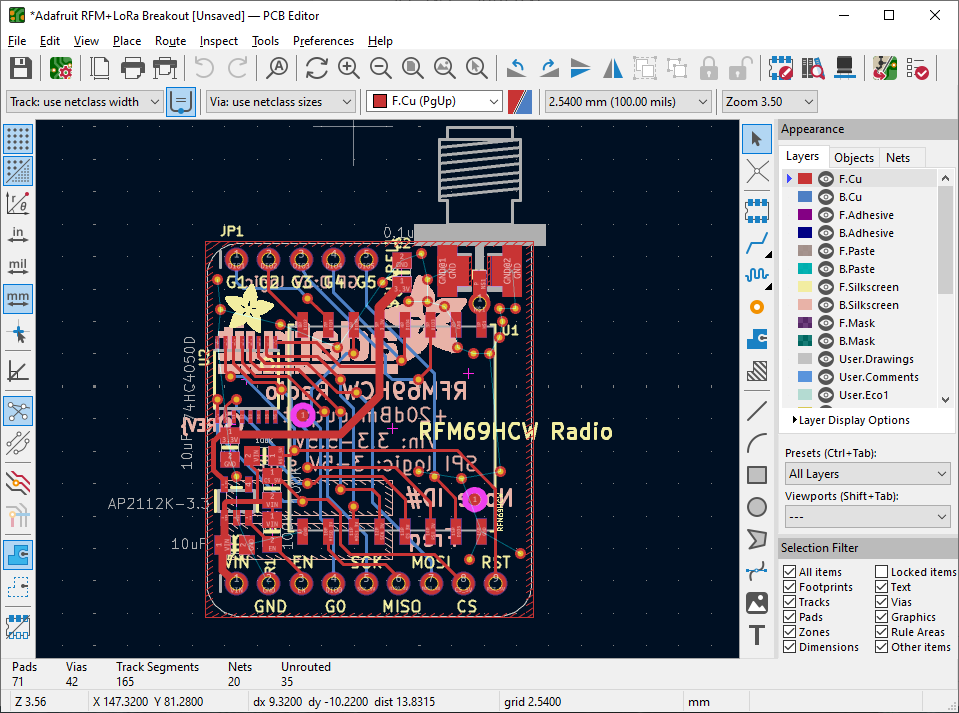
The board design files can be found on GitHub: GitHub - adafruit/Adafruit-RFM-LoRa-Radio-Breakout-PCB: PCB files for the Adafruit RFM/LoRa Radio Breakouts. The headers have 0.1" (2.54mm) pitch. Their exact placement can be determined by opening the Adafruit RFM+LoRa Breakout.brd file in your PCB design tool. I don’t have Eagle installed, but I was able to import it into KiCAD as shown below:
Hello jcollins82,
Please check the Datasheet, as it shows the 2 rows of pins would be 1" apart, as shown in a drawing on page 81.
It also shows it on a breadboard, so the pin spacing is 0.1".