Code Downloads
Ambient Light Sensor Pmod Controller (top level file): ambient_light_sensor.vhd (4.0 KB)
SPI Master (must be included in the project): spi_master.vhd (8.8 KB)
Features
- VHDL source code of a streamlined interface to Digilent’s Ambient Light Sensor Pmod (PmodALS)
- Continually outputs latest ambient light data on a parallel interface
- Handles SPI communication and all data retrieval from the ALS Pmod
- Configurable system clock rate
Introduction
This details a VHDL component that handles interfacing to Digilent’s Ambient Light Sensor Pmod, shown in Figure 1. Figure 2 illustrates a typical example of this ALS Pmod Controller integrated into a system. As shown, the ALS Pmod Controller connects to the Pmod ports and executes transactions to secure ALS data. The data is then presented on a parallel interface which can be connected to user logic or to output ports on the FPGA. This component was designed using Vivado 2017.2. Resource requirements depend on the implementation.

Figure 1. Digilent ALS Pmod

Figure 2. Example Implementation
Background
The ALS Pmod uses Vishay Semiconductor’s ambient light sensor TEMT6000X01 to measure visible light. A Texas Instruments’ analog-to-digital converter ADC081S021 converts the sensor’s output voltage to a digital value and transmits this value over an SPI interface when requested.
Theory of Operation
The ALS Pmod Controller uses the SPI Master component available on eewiki to continually initiate readings and retrieve the resulting data from the ALS Pmod. Once complete, the received data is made available on als_data port, and the controller immediately restarts the process. This results in continually updated ambient light data available to the user with no input required.
The SPI Master is configured with CPOL = 1 and CPHA = 1, to meet the requirements of the SPI slave it communicates with (the ALS Pmod’s ADC). The SPI Master’s enable port is tied high, so the component immediately begins a new transaction one system clock cycle after the current transaction completes.
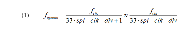
Equation 1 defines the frequency at which the output data updates. This is influenced by the system clock frequency the user provides at the clk input port and the value assigned to the spi_clk_div GENERIC. (See the section Configuring the Clock for details to properly assign spi_clk_div).
The ASL Pmod Controller is set up to provide the fastest update rate available for a given system clock, while keeping the SPI clock rate within its 4 MHz specified upper limit. The fastest rate is ~242 kHz, achieved when the provided system clock is an integer multiple of 8.
Configuring the Clock
The clocking of this ALS Pmod Controller is configured by assigning a value to the GENERIC spi_clk_div, defined in the ENTITY. Equation 2 defines how this value is calculated.

where fclk is the frequency of the provided system clock in MHz. The system clock is provided on the clk input port.
For example, the default value specified in the code is spi_clk_div = 13. This is arrived at because the most common Digilent development kit at the time of this writing, the Basys3, has a system clock of 100 MHz. 100/8 = 12.5, rounded up is 13.
Equation 3 defines the SPI clock frequency fsclk that results.

This calculation keeps the SPI clock at or near the maximum specified SPI communication frequency of 4 MHz (without exceeding it) to provide the maximum ALS data update frequency available with a given system clock.
Port Descriptions
Table 1 describes the ALS Pmod Controller’s ports.
Table 1. Port Descriptions

Connections
This Pmod has a 6-pin connector. Table 2 provides the pinout for this connector. The ALS Pmod Controller’s ports need to be assigned to the FPGA pins that are routed to this connector as listed.
Table 2. ALS Pmod Pinout and Connections to ALS Pmod Controller

Reset
The reset_n input port must have a logic high for the ALS Pmod Controller component to operate. A low logic level on this port asynchronously resets the component. During reset, the component aborts the current transaction with the ALS Pmod and clears the als_data output. Once released from reset, the ALS Pmod Controller resumes operation.
Conclusion
This ALS Pmod Controller is a programmable logic component that interfaces to Digilent’s Ambient Light Sensor (ALS) Pmod. It handles all communication with the ALS Pmod to provide a continual stream of updated ambient light data on a parallel output.