The Creality Hi-Combo comes mostly assembled out of the box. To assemble the printer with the single spool holder there are just seven screws needed and six when using the Creality Filament System (CFS) instead.
The Creality Hi-Combo comes with the CFS on top with the printer underneath a piece of cardboard with instructions on how to remove the printer components.
What is included?

Spool Arm, Spool Barrel, Spool Filament Guide, Hot End Nozzle Wrench, Side-Cutters, Declogging Tool, Grease, Cable Ties, Extra Wiping Pad, 3 lengths of PTFE tubing, North America Power Cord, CFS Buffer, CFS 485 Cable 45cm, CFS 485 Cable 100cm, 2 Cable Covers, Adhesive Strip, Sample PLA filament, Creality Hi Quick Installation Guide, CFS Manual, After Sales Service Card, Creality Stickers
Creality Hi Setup

Once the printer, CFS and the accessories have been removed from the box. Setting up the printer can begin.
Position the gantry with the print head facing down. Holding the cables for the steppers to the gantry and then insert the gantry into the base, with the print head facing the front of the base, this is the side with the screen. There is plenty of room for the cables after they have been connected.
Next plug the connectors from the steppers and the gantry into the their respective mates. The connectors are polarized to insure they are installed correctly.
Next use the four M4x8 screws and the 2.5 mm hex wrench to screw them into the base. There is a plate with holes to the secure the gantry to the base. Here the 2.5mm bit was used from iFixit’s 2434-145392-1-ND. Don’t tighten them fully until all of the remaining screws have been installed securing the base this will help align the gantry.
Once the four M4x8 screws have been installed, move to the back of the printer to the 2 M3x8 screws with the 2.5mm hex wrench. Once they are tightened on either side of the base into the gantry, the previous four screws can be fully tightened.
When the connectors are installed, place the two motor covers over the screws and press down. These will help prevent dust and debris from entering the stepper wells and ensure the cables do not snag. If they need to be removed, use a flat head screw driver two pry them up.
Take the strip of adhesive and remove one side of the backing, place and firmly press the strip to the back of the CFS buffer. Place the buffer on the outside of the right Z-axis cover.
Using one of the two shorter PTFE tubes, insert it in the top of the printer head extruder. With the other end, insert it into the top of the CFS buffer.
With the gantry secured to the base, the power and signal can be connected for the X-axis. Open the cable management clips at the rear of the printer, insert the cable and close them after. After the second clip is secured, now the cable can be inserted into the connector for the X-axis.
Connecting the CFS

CFS Included parts
CFS 100cm 485 cable, CFS 45cm 485 cable, Adhesive, CFS buffer, Quick Installation Guide, 3 PTFE lengths
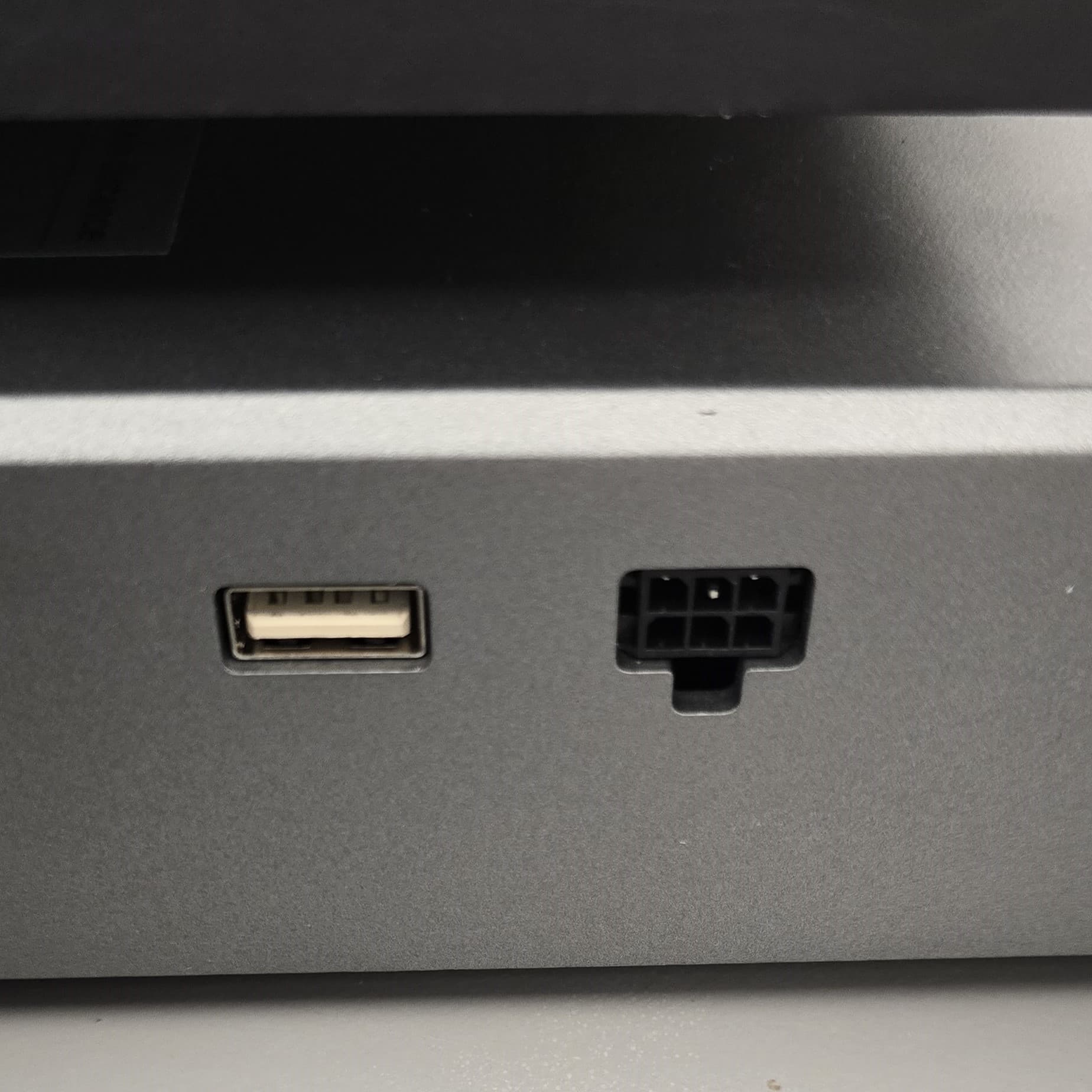
To connect the CFS to the printer, first make sure the printer is off. Then take the CFS 100cm 485 cable and plug it into the right side of the printer next to the USB A port.


Connect the other end of the cable to the rear of the CFS unit. Then take the CFS 45cm cable and plug it into remaining port on the CFS and then connector the other end to the CFS buffer.

Using one of the PTFE tubes insert it into the CFS unit at the back and the other end is to be inserted into the bottom of the CFS buffer in one of the open ports.


Be sure to open the desiccant holders in the CFS and open the sealed clear pouch. The white desiccant pouch is to remain sealed. Place them back in the holder and refit the grill over the desiccant. These will help maintain a dry environment for the filament.
The printer can now be powered on and the filament can be inserted into the CFS.
Single Spool Holder Installation
On top of the printer, Creality has included their recommended location for the spool holder if it is used. Even if the CFS is connected the to printer, having the spool installed can be used when using filaments not supported by the CFS.

If the label for the recommended location of the spool is removed, the edge of the mounting arm is 95mm from the seam of the crossbar and the left gantry upright.


The mount for the arm opens and slides over the cross bar and then the latch is closed, securing the arm to the printer.


Take the filament guide and align the hole for the M3x5 screw, using the 2mm hex wrench tighten the screw to secure the filament guide.


Next insert the spool barrel into the top of the arm and twist it to secure it.
The printer is now setup and can be connected to the Creality Print for more control over the printer including setting filaments in the remotely, cancel print objects and exporting time lapse videos.