Created by Taylor Roorda, last modified on Jul 17, 2019
Introduction

The Microsemi Maker-Board is a low cost evaluation kit featuring the SmartFusion 2 SoC. The SmartFusion 2 combines an ARM Cortex-M3 processor with Microsemi’s flash-based FPGA fabric on a single chip along with many of the peripherals SoC users are accustomed to such as RAM and DSP blocks. The Maker-Board adds on an Ethernet interface, an ambient light sensor, SPI Flash, and some buttons and LEDs. The board also has connections for two different WiFi modules, the ESP32 and the ESP8266, which are not included.
The objective of this guide is to create a demo project that utilizes most of the peripherals on the Maker-Board and to provide a starting point for developing custom applications. This example uses FreeRTOS and an ESP8266 module to create an IoT data logging device.
Availability
- Microsemi Maker Board: M2S010-MKR-KIT (available exclusively through DigiKey)
- ESP8266 Module: 1568-1235-ND
- ESP32 Module: 1738-1294-ND
Resources
The below software is required for this tutorial:
- Microsemi Libero SoC v11.8 or above. The guide uses v11.8 SP1.
- Microsemi SoftConsole v4.0
- FreeRTOS Source
- FreeRTOS Guide
- ESP8266 Command Reference
- Maker Board Schematic - DIGIKEY MAKER KIT REVA1_0_20170606.pdf (446.2 KB)
Note: Make sure to download SoftConsole v4.0 or v5.1. SoftConsole v3.4 does not support the FlashPro 5 programming hardware used on the board. SoftConsole v5.2+ may work, but require significant changes to what is outlined below.
Hardware Configuration
Configuration of the SmartFusion 2 hardware is done through Libero. Since this example does not use any IP in the FPGA, Libero will be used to set up the Cortex-M3 and choose which peripherals will be used.
- Create a new Libero project.
- Select M2S010-TQ144 as the target device.
- Click Next to accept the default Device Settings.
- Choose Create a system builder based design and click Next .
- Click Finish . No HDL sources are required and constraints will be added later.
- If you are prompted to select a constraint flow, choose Enhanced Constraint Flow.
- Libero will ask to name the system. Choose something suitable and click OK .
- System Builder will then open.
- Click Next.
- On the peripherals page, enable MM_UART0 , MM_UART1 , MSS_I2C0 , and MSS_GPIO.
- For each peripheral, click the Configure button to the left of the Enable box. Change the Connect To option to Fabric .
- For the GPIO peripheral, set GPIO 0-7 as Outputs connected to FABRIC_A .
- The circle to the left of MSS Peripherals should now be green indicating the configuration is valid. Click Next.
- From the drop-down menu, select On-chip 25/50 MHz Oscillator as the clock source. Click Next.
- Click Next to accept the default Microcontroller configuration.
- Click Next to accept the default SECDED configuration.
- Click Next to accept the default Security configuration. The advanced security features are only available on “S” suffix parts, which the Maker-Board does not use.
- Click Next to accept the default Interrupt configuration. No fabric interrupts are used in this example.
- Click Next to accept the default Memory Map configuration. No memory mapped peripherals are used in this example.
- Click Finish to create the system. An instance will be created in the block diagram.
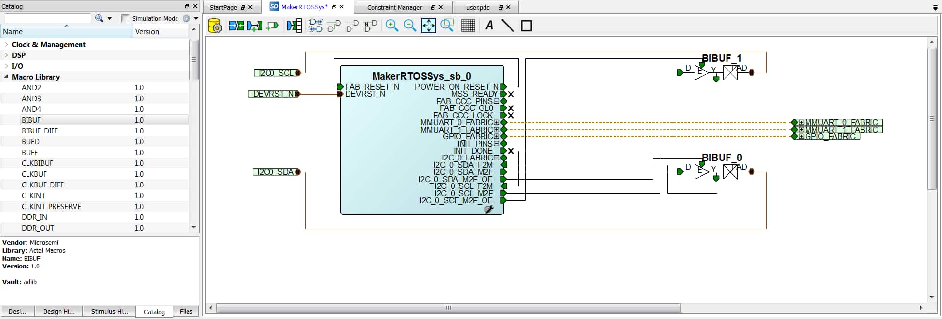
- Open the IP Catalog to the left and expand the Macro Library . Drag two instances of the BIBUF macro to the design.
- Select the MM_UART0 , MM_UART1 , and GPIO_FABRIC interfaces and right-click on them. Choose Promote to Top Level.
- Expand the remaining groups and select INIT_DONE, FAB_CCC_LOCK, FAB_CCC_GL0, and MSS_READY. Right-click on them and choose Mark Unused.
- Connect the remaining signals as shown in the diagram below.
- Save the block diagram and click the Generate Component button to the top left.
- Navigate back to the Design Flow panel on the left. Select Synthesize .
- You will see a number of warnings in the messages that refer to unused components and can be safely ignored.
- When synthesis has completed, select Manage Constraints from the Design Flow panel.
- Choose New → Create New I/O Constraint from Root Module . Libero will auto-generate a constraint file populated with the top-level ports from the block diagram.
- Right-click the generated file and choose Set as Target .
- Select Edit → Edit with I/O Editor .
- Set up the I/O constraints according to the table below. If these settings aren’t available, check the IO Bank settings to set the bank voltages.
- Save the constaints and close the I/O Editor.
- Back in the Design Flow panel, select Place and Route .
- When Place and Route has completed, run Generate FPGA Array Data .
- After the FPGA array data is generated, run Generate Bitstream .
- Connect the Maker-Board to a computer with a USB cable. Choose Run PROGRAM Action to load the configuration onto the board.
- Near the bottom of the Design Flow panel, select Configure Firmware Cores .
- Make sure all the available firmware is selected for generation. There should be one for each peripheral enabled at the beginning. Libero will ask to download any cores that are not already present on the computer.
- From the Design Flow panel, choose Export Firmware. Select SoftConsole4.0 as the Software IDE . Export hardware configuration and firmware drivers should be selected.
- Hardware configuration is now complete.


Software Application
Once the hardware is set up, the software can be developed. As stated previously, this example utilizes FreeRTOS to create an IoT sensor node that uploads data to ThingSpeak. A simple UART bridge is also created to allow a user to manually send AT commands to the ESP8266 module.
Functional Description
This section will provide a brief high-level overview of the four primary tasks in this example program. Some understanding of FreeRTOS will be helpful.
The main() function in this program is responsible for:
- Calling the initialization function for the hardware peripherals (UART, I2C, GPIO).
- Creating the receiving tasks for the two UARTs
- Creating the task to read the I2C sensor
- Creating the task to send sensor data to the WiFi module
- Starting the FreeRTOS scheduler
Once the scheduler is started, the program will alternate between processing the tasks below and interrupts based on priority.
vTaskSpinLEDs() is executed approximately every 85 ms. It simply toggles the SmartFusion 2’s GPIO outputs to create a “spinning” effect on the 8 on board LEDs.
vTaskUARTBridge() is performed each time one or more bytes are received over either UART.
- When a UART interrupt occurs, the interrupt handler ( prvUARTRxNotificationHandler ) will “give” a task notification, signaling that data is available to be read. When the interrupt handler exits, the task will immediately begin executing.
- The task attempts to take a task notification which acts like a semaphore. If there is no notification / data available, the task blocks until that data becomes available.
- When a notification is received, data is copied into a buffer and echoed through the terminal connection on UART0.
- If the data received is from UART0 (terminal) it is accumulated in a buffer until a \n character is received. The accumulated string is then sent to the ESP8266 on UART1.
- If the data received is from UART1 (ESP8266), it is accumulated and checked for either an “OK” or some sort of error and notifies the upload task.
vTaskUARTUploadData() is performed every 20 seconds as long as data is available from the light sensor. It simply formats the AT command strings with the data received from the sensor and sends it to the ESP8266 on UART1. The AT commands used are below. (Ignore comments after the #).
AT+CIPSTART="TCP","184.106.153.149",80                          # Start a TCP connection to the ThingSpeak API server on port 80

AT+CIPSEND=XX                                                   # Declare a transfer of XX bytes to the server

>GET /update?api_key=XXXXXXXXXXXXXXXX&field1=yy&field2=zz        # Send a GET request using a custom API key and two data values

# Server will respond with the number of entries on the channel and close the connection
# +IPD,3:539CLOSED
vTaskReadLightSensor() initializes the I2C sensor the first time it is executed. Each subsequent execution polls the sensor for new data. If new data is available, it is read from the sensor and a notification containing the new data is sent to the upload task for processing. This task will then block for the sampling rate of the sensor (500 ms by default).
Set Up
Before writing any code, there are some initial steps that need to be taken when using SoftConsole v4.0 as outlined in the SoftConsole v4.0 Release Notes. The firmware cores generated in Libero will also need to be imported to the project.
-
Open SoftConsole and choose a convenient directory as the workspace.
-
In SoftConsole, select File → New → C Project .
-
Name the project. Make sure that Cross ARM GCC is selected as the toolchain.
-
Click Next to accept the default configurations.
-
Make sure that the toolchain name is GNU Tools for ARM Embedded Processors (arm-none-eabi-gcc). Click Finish .
-
Once the project is created, right-click on it in the Project Explorer. Select Import. Choose to import a File System.
-
Browse to the directory to where the firmware from Libero was exported. Check the firmware folder to include all the files within it.
-
Choose to copy into a new folder in the project workspace called firmware . Click Finish to import the firmware files into the project.
-
Right-click on the project in the Project Explorer. Select Properties . Expand the C/C++ Build tab and click on Settings .
-
Under Tool Settings → Cross ARM C Linker → General , click the Add.. button near the top right to choose the linker script. The script is located in firmware/CMSIS/startup_gcc/debug-in-microsemi-smartfusion2-esram.ld.
-
Under Tool Settings → Cross ARM C Linker → Miscellaneous , check the Use newlib nano (–specs=nano.specs) box.
-
Under Tool Settings → Cross ARM C Compiler → Miscellaneous → Other compiler flag, enter (without quotes) " –specs=cmsis.specs" .
-
Select the Toolchains tab at the top. Near the bottom, check the Create extended listing option.
-
Click OK to apply the changes.
-
Select Run → Debug Configurations . Double-click GDB OpenOCD Debugging to create a new configuration.
-
Click the Debugger tab. Change the Config options to " –command “set DEVICE M2S010” --file board/microsemi-cortex-m3.cfg"
-
The initial set up is now complete. Later, once the project has been built, the executable will have to be added to the configuration.


Import FreeRTOS
With the set up complete, the next step is to import the FreeRTOS source code into the project. FreeRTOS is not necessary when working with the SmartFusion 2, but can make multitasking easier when scaling the project up to more advanced applications.
-
Download and extract the FreeRTOS source from above to a convenient location.
-
Locate the CORTEX_SmartFusion2_M2S050_SoftConsole directory in the Demo directory of FreeRTOS. Run the CreateProjectDirectoryStructure.bat file to set up the project.
-
In SoftConsole, right-click on the project and select Import. Under General, choose File System . Navigate to the FreeRTOS source directory.
-
Check the entire FreeRTOS-Source directory and also import FreeRTOSConfig. h from the RTOSDemo directory. Other files from the demo may be included to try the official FreeRTOS demo or for reference, but are not necessary for this example.
-
Note : If your build fails with the following errors: undefined reference to
ulGetRunTimeCounterValue’ in tasks.c* and *undefined reference tovConfigureTimerForRunTimeStats’ in tasks.c, include the RunTimeStatsTimer.c file highlighted above. -
Choose a folder in the workspace to import the files into such as ../FreeRTOS . Click Finish to import the files into the project.
-
All FreeRTOS source files should now be available within the project.

Import Example Source Code
Download the source code for the example project at the link below:
Example Source.zip (11.5 KB)
Follow the steps above to import the files into SoftConsole.

Include Paths
At this point all the files for the project should be included, however, attempting to build the project will result in errors about include files not being found. SoftConsole needs to be told where to look for all the header files that were just imported.
- Right-click on the project. Select Properties.
- Expand the C/C++ General section. Select Paths and Symbols .
- Add all of the folders that were imported above as include paths by using Add.. → Workspace → . The end result should look something like:
- SoftConsole should now be able to locate all the necessary header files for compilation.

Connecting to ThingSpeak
To do the complete example project, a free ThingSpeak account is required. ThingSpeak is an IoT data logging platform from MathWorks. This section assumes you have already created an account.
- Create a channel in ThingSpeak with at least 2 data fields. Fill in the other information as necessary. The resulting landing page will look like this, but without any data entries.
- Click on the API Keys tab to view your personal Write API Key . Copy this key.
- Open uart.c in SoftConsole. In the function vTaskUARTUploadData, change the API Key value in ucGetReq[] to the key from above.

uart.c
void vTaskUARTUploadData(void *pvParameters)
{
    const uint8_t ucConnectCmd[] = "AT+CIPSTART=\"TCP\",\"184.106.153.149\",80\r\n";
    const uint8_t ucSendCmd[] = "AT+CIPSEND=";
    const uint8_t ucGetReq[] = "GET /update?api_key=XXXXXXXXXXXXXXXX&field1=";      // Replace this API key with your own
    const uint8_t ucField2[] = "&field2=";
    const uint8_t ucCloseCmd[] = "AT+CIPCLOSE\r\n";
    const uint8_t ucCRLF[] = "\r\n";

    /* ... */
}
Building and Running the Project
At this point, the project should be ready to be built and run on the board. If any errors are received in the compilation, go back and check to make sure everything is as shown in the example.
- In SoftConsole, select Project → Build All (Ctrl + B) to compile the project.
- When the build is finished, select Run → Debug Configurations.
- Click on the Search Project button to look for the .elf file that was just created. It should be the only option.
- Connect the board to the PC with the provided USB cable.
- Click Debug to launch the program on the hardware. You should see the LEDs flashing in a “spinning” pattern.

Using the Demo Program
When first launching the demo program, the FreeRTOS tasks responsible for uploading data to ThingSpeak are disabled. The SmartFusion is then simply acting as a UART bridge between a terminal on a PC and the ESP8266 module plugged into the board. The reason for this is to allow users to manually configure the ESP8266 to connect to a WiFi access point before starting the automated upload tasks. Of course, users can add this functionality into the application code if desired. Once the module has been connected to an access point, it will continue trying to connect to that access point even after power cycling.
Open a terminal program of your choice. The Maker-Board should create 4 sequential COM ports on the computer. The UART connection will be the third one.
Settings are 115200 baud - 8 data bits - 1 stop bit - No parity. Make sure to change your terminal settings to append CR+LF when the enter key is pressed. However, the baud rate may vary depending on the firmware installed on the ESP module.
- Use the following commands to connect to an access point (ignoring the comments after # symbols). Each successful command should return an “OK”.
AT+CWMODE=1                                     # Set the module to station (client) mode

AT+CWLAP                                        # List all visible APs

AT+CWJAP="<SSID>","<PASSWORD>"                  # Join an AP
- When the ESP8266 has been successfully connected to an access point, return to SoftConsole and change the line below in the file main.c :
main.c
/* Standard includes. */
#include <stdio.h>

/* Kernel includes. */
#include "FreeRTOS.h"
#include "task.h"
#include "semphr.h"

/* Driver includes. */
#include "drivers/mss_uart/mss_uart.h"  // For baud rate defines and instances

/* Application includes. */
#include "leds.h"
#include "uart.h"
#include "i2c.h"

/* Set to 1 to enable the upload tasks once the module has been set up */
#define ENABLE_UPLOAD    1                  // Change from 0 to 1

/* ... */
- Rebuild the project. The program will now create the two FreeRTOS tasks that read the I2C ambient light sensor and send that data to ThingSpeak. The SmartFusion 2 should now be sending an update over WiFi approximately every 20 seconds.
Conclusion
This guide provides a FreeRTOS based example program for the Microsemi Maker-Board which utilizes most of the on board peripherals. The example should provide a groundwork for users to develop their own applications, with or without FreeRTOS.
Additional Information
The University of California, Irvine has developed their own demo project in conjunction with Microsemi for the Maker-Board which includes examples for the ESP32 as well as the ESP8266. Their work is documented on their GitHub page below:
The following guide details a similar setup for the Maker-Board, but without the WiFi and FreeRTOS elements. It also includes a slightly different programming method.
Getting started with the M2S010-MKR-KIT on Github
Questions/Comments
Any questions or comments please go to DigiKey’s TechForum