Availability
The original version of the MachXO2 Breakout Board featured an LCMXO2-1200ZE-1TG144C CPLD, which has now been replaced on a new version of the board by an LCMXO2-7000HE-4TG144C.
The new version of the MachXO2 breakout board (LCMXO2-7000HE-B-EVN) is available from Digi-Key here.
The old version of the MachXO2 breakout board (LCMXO2-1200ZE-B-EVN) is available while supplies last from Digi-Key here.
VHDL Code for Tutorial
blinking_led.vhd (2.0 KB)
Introduction
This introduction to the Lattice Diamond software (version 4.1.87) walks through creating a simple project for the MachXO2 Breakout Board Evaluation Kit. It works with either version of the kit. Topics include starting a new project, code entry, using the internal oscillator, compiling, making pin assignments, and programming the board. There is a separate tutorial that covers simulation here.
Creating a New Project
To create a new project, select File → New → Project…, and the New Project Wizard launches. Click Next. Enter a project name and location as shown in Figure 1, and click Next.
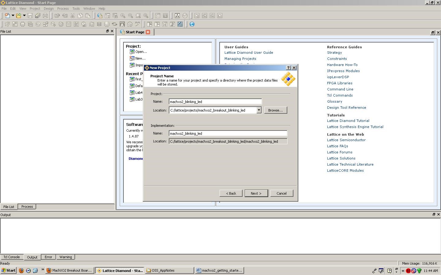
Figure 1. Entering the project name and location.
This project does not use pre-existing source files. Click Next.
Specify the device family as MachXO2, the device as LCMXO2-7000HE or LCMXO2-1200ZE (depending on which version of board you have), the package type as TQFP144, the performance grade as 4 (if using the 7000HE) or 1 (if using the 1200ZE), and the operating conditions as Commercial. Some of these criteria must be selected before others for the proper options to populate in the drop-down lists. The complete part number, LCMXO2-7000HE-4TG144C or LCMXO2-1200ZE-1TG144C, appears in the part name text box as depicted in Figure 2. Click Next. Click Finish.

Figure 2. Selecting the device.
Code Entry and Instantiating the Internal Oscillator
To create a new source file, select File → New → File…. Select the category Source Files and the source file type VHDL Files as shown in Figure 3. Name the new file and click New.

Figure 3. Creating a VHDL file.
The provided blinking_led.vhd example code uses the MachXO2’s internal oscillator to toggle an LED twice per second. To use the oscillator OSCH primitive, either the “lattice” or the “machxo2” library must be instantiated:
LIBRARY lattice;
USE lattice.components.all;

LIBRARY machxo2;
USE machxo2.all;
The OSCH component is declared as follows:
COMPONENT OSCH
  GENERIC(
    NOM_FREQ: string := "53.20");  --53.20MHz, or can select other supported frequencies
  PORT(
    STDBY    : IN  STD_LOGIC;      --'0' OSC output is active, '1' OSC output off
    OSC      : OUT STD_LOGIC;      --the oscillator output
    SEDSTDBY : OUT STD_LOGIC);     --required only for simulation when using standby
END COMPONENT;
For this example project, the OSCH instance is instantiated as follows:
OSCInst0: OSCH
   GENERIC MAP (NOM_FREQ  => "53.20")
   PORT MAP (STDBY => '0', OSC => clk, SEDSTDBY => OPEN);
See the appendix at the bottom of this page for a list of OSCH supported frequencies.
Pin Assignments and Compilation
Select the Process Pane as depicted in Figure 4. Double-click on Translate Design in the Process pane to perform synthesis and translation.
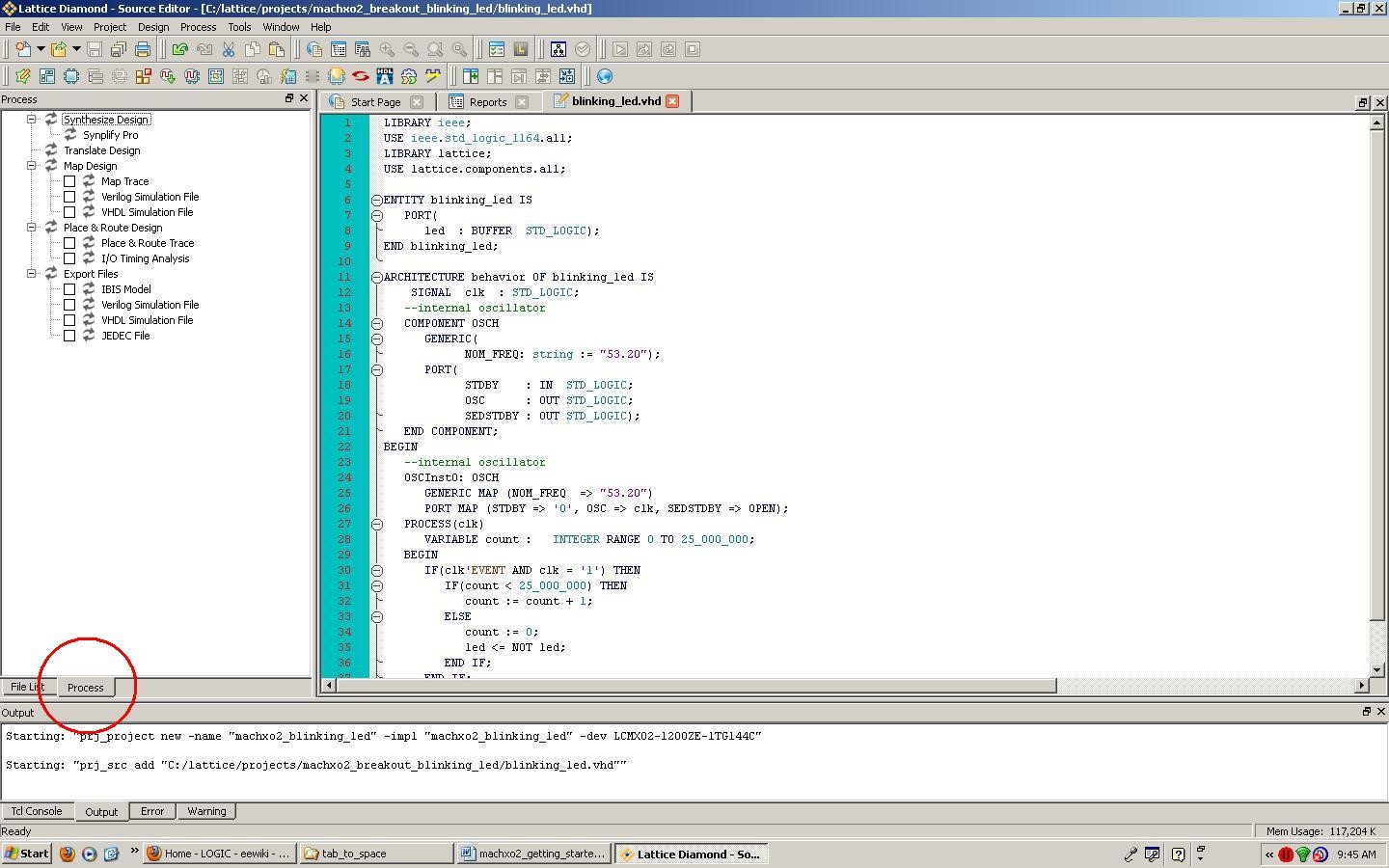
Figure 4. Selecting the Process pane.
Select Tools → Spreadsheet View. Click on the Pin Assignments tab at the bottom of the Spreadsheet View. Scroll down until Pin 107 appears. Double-click in the Signal Name column of Pin 107. The Assign Signals dialog box appears as shown in Figure 5.

Figure 5. Assigning pins.
Select the led signal and click Assign Signals to assign it to pin 107. Pin 107 is connected to LED D8 on the MachXO2 breakout board. Figure 6 shows the resulting signal assignment.

Figure 6. Assigning pins completed.
Return to the Process pane, check JEDEC File under Export Files. Double-click on Export Files to Map, Place & Route, and create the JEDEC programming file. If asked to save modified files, do so. Figure 7 illustrates the successful outcome.
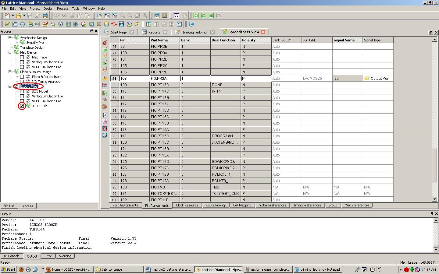
Figure 7. Successful Compilation
Programming the CPLD
Plug the MachXO2 breakout board into the computer via the USB cable.
Select Tools → Programmer. The Programmer: Getting Started dialog box opens as shown in Figure 8. Click OK.

Figure 8. Opening the programmer.
Click the Program icon. The device programs. Once complete, the Status indication turns green as depicted in Figure 9. LED D8 on the MachXO2 breakout board blinks once per second.

Figure 9. Programming completed successfully.
Conclusion
This introduction to the Lattice Diamond software and the MachXO2 breakout board demonstrates the essential steps to create a simple project with these tools.
Appendix: OSCH Supported Frequencies
The default frequency is 2.08MHz. Supported frequencies (in MHz) include:
2.08        4.16         8.31        15.65

2.15        4.29         8.58        16.63

2.22        4.43         8.87        17.73

2.29        4.59         9.17        19.00

2.38        4.75         9.50        20.46

2.46        4.93         9.85        22.17

2.56        5.12        10.23        24.18

2.66        5.32        10.64        26.60

2.77        5.54        11.08        29.56

2.89        5.78        11.57        33.25

3.02        6.05        12.09        38.00

3.17        6.33        12.67        44.33

3.33        6.65        13.30        53.20

3.50        7.00        14.00        66.50

3.69        7.39        14.78        88.67

3.91        7.82        15.65       133.00