This article will describe how to create a Zephyr IoT weather station using the Nordic nRF54L15-DK development kit

connected to an Adafruit BME280 Humidity + Barometric Pressure + Temperature Sensor Breakout Evaluation Board available from DigiKey.

This Adafruit BME280 Humidity + Barometric Pressure + Temperature Sensor Breakout Evaluation Board contains a Bosch BME 280 sensor that in this case is used to communicate via 4-wire SPI interface at 1 MHz. The Bosch BME 280 sensor can also be interfaced via I2C and this board has the QWIC provision (Please see previous Zephyr I2C interface article in case this interface is used). The Adafruit BME280 Humidity + Barometric Pressure + Temperature Sensor Breakout Evaluation Board was soldered to the pins and attached to a breadboard similar to this one available from DigiKey,

The following color coded jumper wires,

were used to make the interconnections between the breadboard and the Nordic nRF54L15-DK development kit.
Before attempting to complete this Zephyr IoT weather station demo, please refer to the following article that describes how to install the software tools needed to develop in Zephyr using a Linux host. Here is the setup with the Sparkfun Logic Analyzer used in this case (Not the optimum one due to long cables, etc),
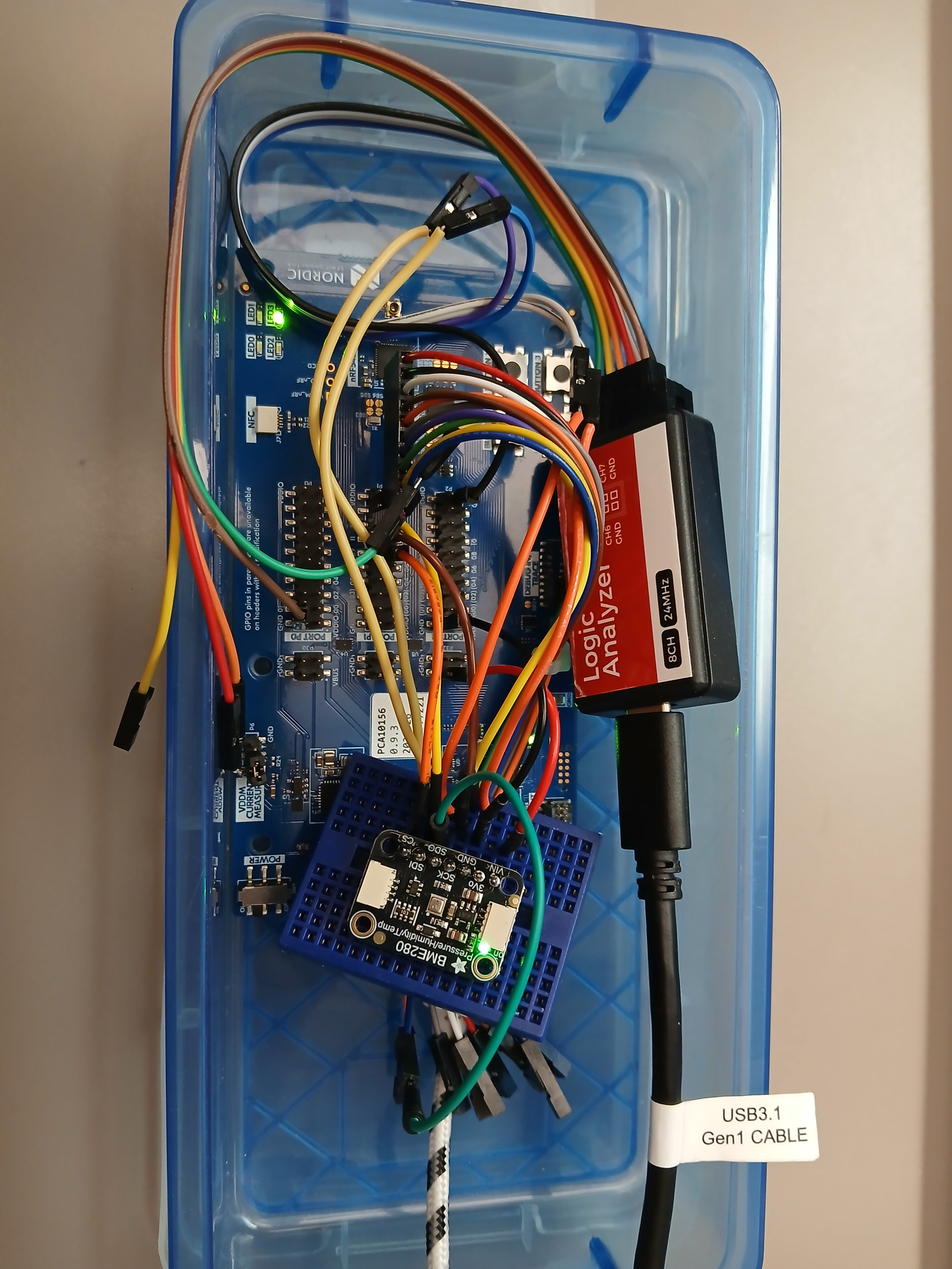
The 4 wire SPI interface connections plus the voltage source line and ground for this demo are summarized as follows,

Create the following Zephyr configuration file called proj.conf,
CONFIG_GPIO=y

CONFIG_CBPRINTF_FP_SUPPORT=y

CONFIG_SPI=y

CONFIG_LOG=y
Per standard Zephyr development procedure, then include the CMakeLists.txt file inside the project folder,
cmake_minimum_required(VERSION 3.20.0)
find_package(Zephyr REQUIRED HINTS $ENV{ZEPHYR_BASE})
project(spi)

target_sources(app PRIVATE src/main.c)
Also include the Zephyr overlay file that defines the 4 wire SPI interface called nrf54l15dk_nrf54l15.overlay
&spi21 {
    compatible = "nordic,nrf-spim";
	status = "okay";
	pinctrl-0 = <&spi21_default>;
	pinctrl-1 = <&spi21_sleep>;
	pinctrl-names = "default", "sleep";
	cs-gpios = <&gpio1 8 GPIO_ACTIVE_LOW>;
	bme280: bme280@0 {
		compatible = "bosch,bme280";
		reg = <0>;
		spi-max-frequency = <1000000>; // 1MHz
	};
};

/* STEP 2.2 - Change the pin configuration */

/*  */
&pinctrl {
	spi21_default: spi21_default {
		group1 {
				psels = <NRF_PSEL(SPIM_SCK, 1, 11)>,
						<NRF_PSEL(SPIM_MOSI, 1, 13)>,
						<NRF_PSEL(SPIM_MISO, 1, 14)>;
		};
	};

	spi21_sleep: spi21_sleep {
		group1 {
				psels = <NRF_PSEL(SPIM_SCK, 1, 11)>,
						<NRF_PSEL(SPIM_MOSI, 1, 13)>,
						<NRF_PSEL(SPIM_MISO, 1, 14)>;
				low-power-enable;
		};
	};
};
The following Zephyr weather station IoT application file called main.c will read the values from the Adafruit BME280 Humidity + Barometric Pressure + Temperature Sensor Breakout Evaluation Board once per second, plus blinks a green LED in the board too,
/*
* Copyright (c) 2024 Nordic Semiconductor ASAhttps://www.digikey.com/en/products/filter/lcd-oled-graphic/107?s=N4IgTCBcDaICYEsDOAHANgQwJ5JAXQF8g
*
* SPDX-License-Identifier: LicenseRef-Nordic-5-Clause
*/
#include <zephyr/kernel.h>
#include <zephyr/logging/log.h>
/* STEP 1.2 - Include the header files for SPI, GPIO and devicetree */
#include <zephyr/device.h>
#include <zephyr/devicetree.h>
#include <zephyr/drivers/gpio.h>
#include <zephyr/drivers/spi.h>
LOG_MODULE_REGISTER(DigiKey_Coffee_Cup, LOG_LEVEL_INF);
#define DELAY_REG 10
#define DELAY_PARAM 50
#define DELAY_VALUES 1000
#define LED0 13
#define CTRLHUM 0xF2
#define CTRLMEAS 0xF4
#define CALIB00 0x88
#define CALIB26 0xE1
#define ID 0xD0
#define PRESSMSB 0xF7
#define PRESSLSB 0xF8
#define PRESSXLSB 0xF9
#define TEMPMSB 0xFA
#define TEMPLSB 0xFB
#define TEMPXLSB 0xFC
#define HUMMSB 0xFD
#define HUMLSB 0xFE
#define DUMMY 0xFF
const struct gpio_dt_spec ledspec = GPIO_DT_SPEC_GET(DT_NODELABEL(led0), gpios);
/* STEP 3 - Retrieve the API-device structure */
#define SPIOP SPI_WORD_SET(8) | SPI_TRANSFER_MSB
struct spi_dt_spec spispec = SPI_DT_SPEC_GET(DT_NODELABEL(bme280), SPIOP, 0);
/* Data structure to store BME280 data */
struct bme280_data {
/* Compensation parameters */
uint16_t dig_t1;
int16_t dig_t2;
int16_t dig_t3;
uint16_t dig_p1;Bosch BME 280 sensor
int16_t dig_p2;
int16_t dig_p3;
int16_t dig_p4;
int16_t dig_p5;
int16_t dig_p6;
int16_t dig_p7;
int16_t dig_p8;
int16_t dig_p9;
uint8_t dig_h1;
int16_t dig_h2;
uint8_t dig_h3;
int16_t dig_h4;
int16_t dig_h5;
int8_t dig_h6;
/* Compensated values */
int32_t comp_temp;
uint32_t comp_press;
uint32_t comp_humidity;
/* Carryover between temperature and pressure/humidity compensation */
int32_t t_fine;
uint8_t chip_id;
} bmedata;
static int bme_read_reg(uint8_t reg, uint8_t *data, uint8_t size)
{
int err;
/* STEP 4.1 - Set the transmit and receive buffers */
uint8_t tx_buffer = reg;
struct spi_buf tx_spi_buf = {.buf = (void *)&tx_buffer, .len = 1};
struct spi_buf_set tx_spi_buf_set = {.buffers = &tx_spi_buf, .count = 1};
struct spi_buf rx_spi_bufs = {.buf = data, .len = size};
struct spi_buf_set rx_spi_buf_set = {.buffers = &rx_spi_bufs, .count = 1};
/* STEP 4.2 - Call the transceive function */
err = spi_transceive_dt(&spispec, &tx_spi_buf_set, &rx_spi_buf_set);
if (err < 0) {
LOG_ERR("spi_transceive_dt() failed, err: %d", err);
return err;
}
return 0;
}
static int bme_write_reg(uint8_t reg, uint8_t value)
{
int err;
/* STEP 5.1 - declare a tx buffer having register address and data */
uint8_t tx_buf[] = {(reg & 0x7F), value};
struct spi_buf tx_spi_buf = {.buf = tx_buf, .len = sizeof(tx_buf)};
struct spi_buf_set tx_spi_buf_set = {.buffers = &tx_spi_buf, .count = 1};
/* STEP 5.2 - call the spi_write_dt function with SPISPEC to write buffers */
err = spi_write_dt(&spispec, &tx_spi_buf_set);
if (err < 0) {
LOG_ERR("spi_write_dt() failed, err %d", err);
return err;
}
return 0;
}
void bme_calibrationdata(void)
{
/* Set data size of 3 as the first byte is dummy using bme_read_reg() */
uint8_t values[3];
uint8_t size = 3;
uint8_t regaddr;
LOG_INF("-------------------------------------------------------------");
LOG_INF("bme_read_calibrationdata: Reading from calibration registers:");
/* STEP 6 - We are using bme_read_reg() to read required number of bytes from
respective register(s) and put values to construct compensation parameters */
regaddr = CALIB00;
bme_read_reg(regaddr, values, size);
bmedata.dig_t1 = ((uint16_t)values[2])<<8 | values[1];
LOG_INF("\tReg[0x%02x] %d Bytes read: Param T1 = %d", regaddr, size-1, bmedata.dig_t1);
k_msleep(DELAY_PARAM);
regaddr += 2;
bme_read_reg(regaddr, values, size);
bmedata.dig_t2 = ((uint16_t)values[2])<<8 | values[1];
LOG_INF("\tReg[0x%02x] %d Bytes read: Param Param T2 = %d", regaddr, size-1, bmedata.dig_t2);
k_msleep(DELAY_PARAM);
regaddr += 2;
bme_read_reg(regaddr, values, size);
bmedata.dig_t3 = ((uint16_t)values[2])<<8 | values[1];
LOG_INF("\tReg[0x%02x] %d Bytes read: Param T3 = %d", regaddr, size-1, bmedata.dig_t3);
k_msleep(DELAY_PARAM);
regaddr += 2;
bme_read_reg(regaddr, values, size);
bmedata.dig_p1 = ((uint16_t)values[2])<<8 | values[1];
LOG_INF("\tReg[0x%02x] %d Bytes read: Param P1 = %d", regaddr, size-1, bmedata.dig_p1);
k_msleep(DELAY_PARAM);
regaddr += 2;
bme_read_reg(regaddr, values, size);
bmedata.dig_p2 = ((uint16_t)values[2])<<8 | values[1];
LOG_INF("\tReg[0x%02x] %d Bytes read: Param P2 = %d", regaddr, size-1, bmedata.dig_p2);
k_msleep(DELAY_PARAM);
regaddr += 2;
bme_read_reg(regaddr, values, size);
bmedata.dig_p3 = ((uint16_t)values[2])<<8 | values[1];
LOG_INF("\tReg[0x%02x] %d Bytes read: Param P3 = %d", regaddr, size-1, bmedata.dig_p3);
k_msleep(DELAY_PARAM);
regaddr += 2;
bme_read_reg(regaddr, values, size);
bmedata.dig_p4 = ((uint16_t)values[2])<<8 | values[1];
LOG_INF("\tReg[0x%02x] %d Bytes read: Param P4 = %d", regaddr, size-1, bmedata.dig_p4);
k_msleep(DELAY_PARAM);
regaddr += 2;
bme_read_reg(regaddr, values, size);
bmedata.dig_p5 = ((uint16_t)values[2])<<8 | values[1];
LOG_INF("\tReg[0x%02x] %d Bytes read: Param P5 = %d", regaddr, size-1, bmedata.dig_p5);
k_msleep(DELAY_PARAM);
regaddr += 2;
bme_read_reg(regaddr, values, size);
bmedata.dig_p6 = ((uint16_t)values[2])<<8 | values[1];
LOG_INF("\tReg[0x%02x] %d Bytes read: Param P6 = %d", regaddr, size-1, bmedata.dig_p6);
k_msleep(DELAY_PARAM);
regaddr += 2;
bme_read_reg(regaddr, values, size);
bmedata.dig_p7 = ((uint16_t)values[2])<<8 | values[1];
LOG_INF("\tReg[0x%02x] %d Bytes read: Param P7 = %d", regaddr, size-1, bmedata.dig_p7);
k_msleep(DELAY_PARAM);
regaddr += 2;
bme_read_reg(regaddr, values, size);
bmedata.dig_p8 = ((uint16_t)values[2])<<8 | values[1];
LOG_INF("\tReg[0x%02x] %d Bytes read: Param P8 = %d", regaddr, size-1, bmedata.dig_p8);
k_msleep(DELAY_PARAM);
regaddr += 2;
bme_read_reg(regaddr, values, size);
bmedata.dig_p9 = ((uint16_t)values[2])<<8 | values[1];
LOG_INF("\tReg[0x%02x] %d Bytes read: Param P9 = %d", regaddr, size-1, bmedata.dig_p9);
k_msleep(DELAY_PARAM);
regaddr += 3; size=2; /* only read one byte for H1 (see datasheet) */
bme_read_reg(regaddr, values, size);
bmedata.dig_h1 = (uint8_t)values[1];
LOG_INF("\tReg[0x%02x] %d Bytes read: Param H1 = %d", regaddr, size-1, bmedata.dig_h1);
k_msleep(DELAY_PARAM);
regaddr += 64; size=3; /* read two bytes for H2 */
bme_read_reg(regaddr, values, size);
bmedata.dig_h2 = ((uint16_t)values[2])<<8 | values[1];
LOG_INF("\tReg[0x%02x] %d Bytes read: Param H2 = %d", regaddr, size-1, bmedata.dig_h2);
k_msleep(DELAY_PARAM);
regaddr += 2; size=2; /* only read one byte for H3 */
bme_read_reg(regaddr, values, size);
bmedata.dig_h3 = (uint8_t)values[1];
LOG_INF("\tReg[0x%02x] %d Bytes read: Param H3 = %d", regaddr, size-1, bmedata.dig_h3);
k_msleep(DELAY_PARAM);
regaddr += 1; size=3; /* read two bytes for H4 */
bme_read_reg(regaddr, values, size);
bmedata.dig_h4 = ((uint16_t)values[1])<<4 | (values[2] & 0x0F);
LOG_INF("\tReg[0x%02x] %d Bytes read: Param H4 = %d", regaddr, size-1, bmedata.dig_h4);
k_msleep(DELAY_PARAM);
regaddr += 1;
bme_read_reg(regaddr, values, size);
bmedata.dig_h5 = ((uint16_t)values[2])<<4 | ((values[1] >> 4) & 0x0F);
LOG_INF("\tReg[0x%02x] %d Bytes read: Param H5 = %d", regaddr, size-1, bmedata.dig_h5);
k_msleep(DELAY_PARAM);
regaddr += 2; size=2; /* only read one byte for H6 */
bme_read_reg(regaddr, values, 2);
bmedata.dig_h6 = (uint8_t)values[1];
LOG_INF("\tReg[0x%02x] %d Bytes read: Param H6 = %d", regaddr, size-1, bmedata.dig_h6);
k_msleep(DELAY_PARAM);
LOG_INF("-------------------------------------------------------------");
}
int bme_print_registers(void)
{
uint8_t buf[2];
uint8_t size = 2; /* size=2 as 1st byte is dummy using bme_read_reg() */
uint8_t data;
int err;
/* STEP 7 - Go through the following code and see how we are using
bme_read_reg() to read and print different registers (1-byte) */
/* Register addresses to read from (see the data sheet) */
uint8_t reg_id = ID;
uint8_t regs_morecalib[16];
uint8_t regs_more[12];
/* Set the register addresses */
regs_morecalib[0] = CALIB26;
for (uint8_t i=0; i<15; i++)
regs_morecalib[i+1] = regs_morecalib[i] + 1;
regs_more[0] = CTRLHUM;
for (uint8_t i=0; i<11; i++)
regs_more[i+1] = regs_more[i] + 1;
/* Read 1 byte data from each register and print */
LOG_INF("bme_print_registers: Reading all BME280 registers (one by one)");
err = bme_read_reg(reg_id, buf, size);
if (err < 0)
{
LOG_INF("Error in bme_read_reg(), err: %d", err);
return err;
}
data = buf[1];
bmedata.chip_id = data;
LOG_INF("\tReg[0x%02x] = 0x%02x", reg_id, data);
k_msleep(DELAY_REG);
/* Reading from more calibration registers */
for (uint8_t i = 0; i < sizeof(regs_morecalib); i++)
{
err = bme_read_reg(regs_morecalib[i], buf, size);
if (err < 0)
{
LOG_INF("Error in bme_read_reg(), err: %d", err);
return err;
}
data = buf[1];
LOG_INF("\tReg[0x%02x] = 0x%02x", regs_morecalib[i], data);
k_msleep(DELAY_REG);
}
/* Reading from more registers */
for (uint8_t i=0; i<sizeof(regs_more); i++)
{
err = bme_read_reg(regs_more[i], buf, size);
if (err < 0)
{
LOG_INF("Error in bme_read_reg(), err: %d", err);
return err;
}
data = buf[1];
LOG_INF("\tReg[0x%02x] = 0x%02x", regs_more[i], data);
k_msleep(DELAY_REG);
}
LOG_INF("-------------------------------------------------------------");
return 0;
}
/* STEP 8 - Go through the compensation functions and
note that they use the compensation parameters from
the bme280_data structure and then store back the compensated value */
static void bme280_compensate_temp(struct bme280_data *data, int32_t adc_temp)
{
int32_t var1, var2;
var1 = (((adc_temp >> 3) - ((int32_t)data->dig_t1 << 1)) *
((int32_t)data->dig_t2)) >> 11;
var2 = (((((adc_temp >> 4) - ((int32_t)data->dig_t1)) *
((adc_temp >> 4) - ((int32_t)data->dig_t1))) >> 12) *
((int32_t)data->dig_t3)) >> 14;
data->t_fine = var1 + var2;
data->comp_temp = (data->t_fine * 5 + 128) >> 8;
}
static void bme280_compensate_press(struct bme280_data *data, int32_t adc_press)
{
int64_t var1, var2, p;
var1 = ((int64_t)data->t_fine) - 128000;
var2 = var1 * var1 * (int64_t)data->dig_p6;
var2 = var2 + ((var1 * (int64_t)data->dig_p5) << 17);
var2 = var2 + (((int64_t)data->dig_p4) << 35);
var1 = ((var1 * var1 * (int64_t)data->dig_p3) >> 8) +
((var1 * (int64_t)data->dig_p2) << 12);
var1 = (((((int64_t)1) << 47) + var1)) * ((int64_t)data->dig_p1) >> 33;
/* Avoid exception caused by division by zero */
if (var1 == 0) {
data->comp_press = 0U;
return;
}
p = 1048576 - adc_press;
p = (((p << 31) - var2) * 3125) / var1;
var1 = (((int64_t)data->dig_p9) * (p >> 13) * (p >> 13)) >> 25;
var2 = (((int64_t)data->dig_p8) * p) >> 19;
p = ((p + var1 + var2) >> 8) + (((int64_t)data->dig_p7) << 4);
data->comp_press = (uint32_t)p;
}
static void bme280_compensate_humidity(struct bme280_data *data, int32_t adc_humidity)
{
int32_t h;
h = (data->t_fine - ((int32_t)76800));
h = ((((adc_humidity << 14) - (((int32_t)data->dig_h4) << 20) -
(((int32_t)data->dig_h5) * h)) + ((int32_t)16384)) >> 15) *
(((((((h * ((int32_t)data->dig_h6)) >> 10) * (((h *
((int32_t)data->dig_h3)) >> 11) + ((int32_t)32768))) >> 10) +
((int32_t)2097152)) * ((int32_t)data->dig_h2) + 8192) >> 14);
h = (h - (((((h >> 15) * (h >> 15)) >> 7) *
((int32_t)data->dig_h1)) >> 4));
h = (h > 419430400 ? 419430400 : h);
data->comp_humidity = (uint32_t)(h >> 12);
}
int bme_read_sample(void)
{
int err;
int32_t datap = 0, datat = 0, datah = 0;
float pressure_pa = 0.0f, temperature_c = 0.0f, humidity = 0.0f;
/* STEP 9.1 - Store register addresses to do burst read */
uint8_t regs[] = {PRESSMSB, PRESSLSB, PRESSXLSB, \
TEMPMSB, TEMPLSB, TEMPXLSB, \
HUMMSB, HUMLSB, DUMMY}; //0xFF is dummy reg
uint8_t readbuf[sizeof(regs)];
/* STEP 9.2 - Set the transmit and receive buffers */
struct spi_buf tx_spi_buf = {.buf = (void *)®s, .len = sizeof(regs)};
struct spi_buf_set tx_spi_buf_set = {.buffers = &tx_spi_buf, .count = 1};
struct spi_buf rx_spi_bufs = {.buf = readbuf, .len = sizeof(regs)};
struct spi_buf_set rx_spi_buf_set = {.buffers = &rx_spi_bufs, .count = 1};
/* STEP 9.3 - Use spi_transceive() to transmit and receive at the same time */
err = spi_transceive_dt(&spispec, &tx_spi_buf_set, &rx_spi_buf_set);
if (err < 0) {
LOG_ERR("spi_transceive_dt() failed, err: %d", err);
return err;
}
/* Put the data read from registers into actual order (see datasheet) */
/* Uncompensated pressure value */
datap = (readbuf[1] << 12) | (readbuf[2] << 4) | ((readbuf[3] >> 4) & 0x0F);
/* Uncompensated temperature value */
datat = (readbuf[4] << 12) | (readbuf[5] << 4) | ((readbuf[6] >> 4) & 0x0F);
/* Uncompensated humidity value */
datah = (readbuf[7] << 8) | (readbuf[8]);
/* Compensate values using given functions */
bme280_compensate_press(&bmedata,datap);
bme280_compensate_temp(&bmedata, datat);
bme280_compensate_humidity(&bmedata, datah);
/* Convert to proper format as per data sheet */
pressure_pa = (float)bmedata.comp_press/256.0f;
float pressure_in = 0.0002953f * pressure_pa;
temperature_c = (float)bmedata.comp_temp/100.0f;
float temperature_f = (1.8f*temperature_c) + 32.0f;
humidity = (float)bmedata.comp_humidity/1024.0f;
/* Print the uncompensated and compensated values */
LOG_INF("\tTemperature: \t uncomp = %d C \t comp = %8.2f C", datat, (double)temperature_c);
LOG_INF("\tTemperature: \t uncomp = %d C \t comp = %8.2f F", datat, (double)temperature_f);
LOG_INF("\tPressure: \t uncomp = %d Pa \t comp = %8.2f Pa", datap, (double)pressure_pa);
LOG_INF("\tPressure: \t uncomp = %d Pa \t comp = %8.2f in Hg", datap, (double)pressure_in);
LOG_INF("\tHumidity: \t uncomp = %d RH \t comp = %8.2f %%RH", datah, (double)humidity);
return 0;
}
int main(void)
{
int err;
err = gpio_is_ready_dt(&ledspec);
if (!err) {
LOG_ERR("Error: GPIO device is not ready, err: %d", err);
return 0;
}
/* STEP 10.1 - Check if SPI and GPIO devices are ready */
err = spi_is_ready_dt(&spispec);
if (!err) {
LOG_ERR("Error: SPI device is not ready, err: %d", err);
return 0;
}
gpio_pin_configure_dt(&ledspec, GPIO_OUTPUT_ACTIVE);
/* STEP 10.2 - Read calibration data */
bme_calibrationdata();
/* STEP 10.3 - Write sampling parameters and read and print the registers */
bme_write_reg(CTRLHUM, 0x04);
bme_write_reg(CTRLMEAS, 0x93);
bme_print_registers();
LOG_INF("Continuously read sensor samples, compensate, and display");
while(1){
/* STEP 10.4 - Continuously read sensor samples and toggle led */
bme_read_sample();
gpio_pin_toggle_dt(&ledspec);
k_msleep(DELAY_VALUES);
}
return 0;
}
The Zephyr project folder should look like this,
|-- CMakeLists.txt
|-- nrf54l15dk_nrf54l15.overlay
|-- prj.conf
`-- src
    |-- main.c
Now proceed to build this Zephyr project as follows in the python virtual environment,
digikey_coffee_cup (venv) $ west build -p always -b nrf54l15dk/nrf54l15/cpuapp -- -DEXTRA_DTC_OVERLAY_FILE=nrf54l15dk_nrf54l15.overlay
Finally connect the nRF54L15-DK Nordic Development kit via the USB interface to flash it,
digikey_coffee_cup (venv) $ west flash
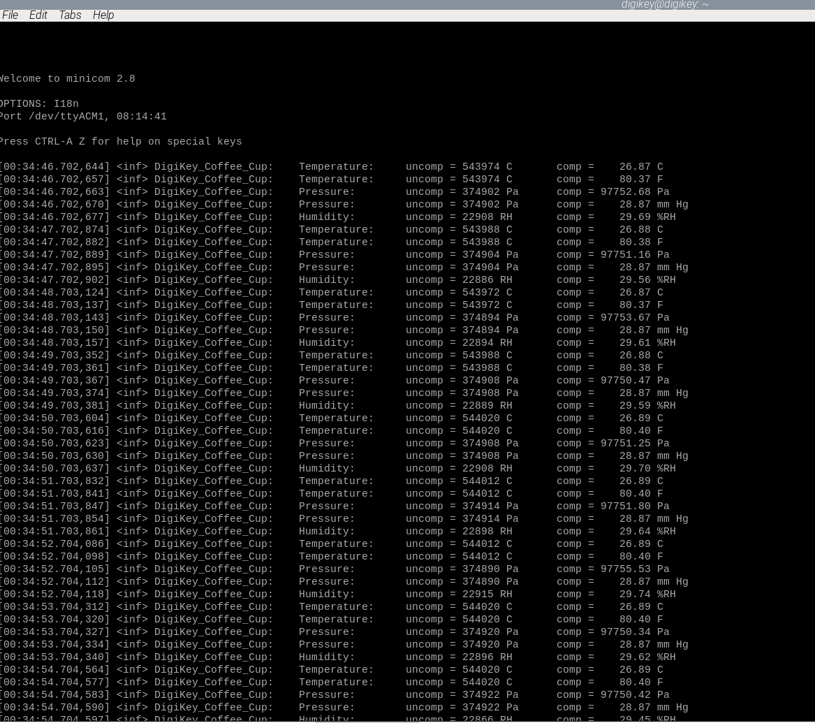
This Zephyr IoT weather station program performs the classical Bosch BME 280 sensor compensations during the initialization stage and then proceeds to read the temperature, humidity and atmospheric pressure values from the sensor and toggles a green LED in the board once per second. This program also performs some classical conversions to display floating point weather parameters in different units. (That is why CONFIG_CBPRINTF_FP_SUPPORT=y is needed).
At this moment, open a minicom terminal to see the weather parameters that are being acquired by the Nordic nRF54L15-DK development kit as follows,
digikey_coffee_cup@digikey:~ $ minicom -D /dev/ttyACM1
The Sparkfun Logic Analyzer was used in the 4 wire SPI interface to monitor these messages as follows. The first snapshot shows all the messages interchanged during the initialization, compensation stage and reading calibration registers from the device,

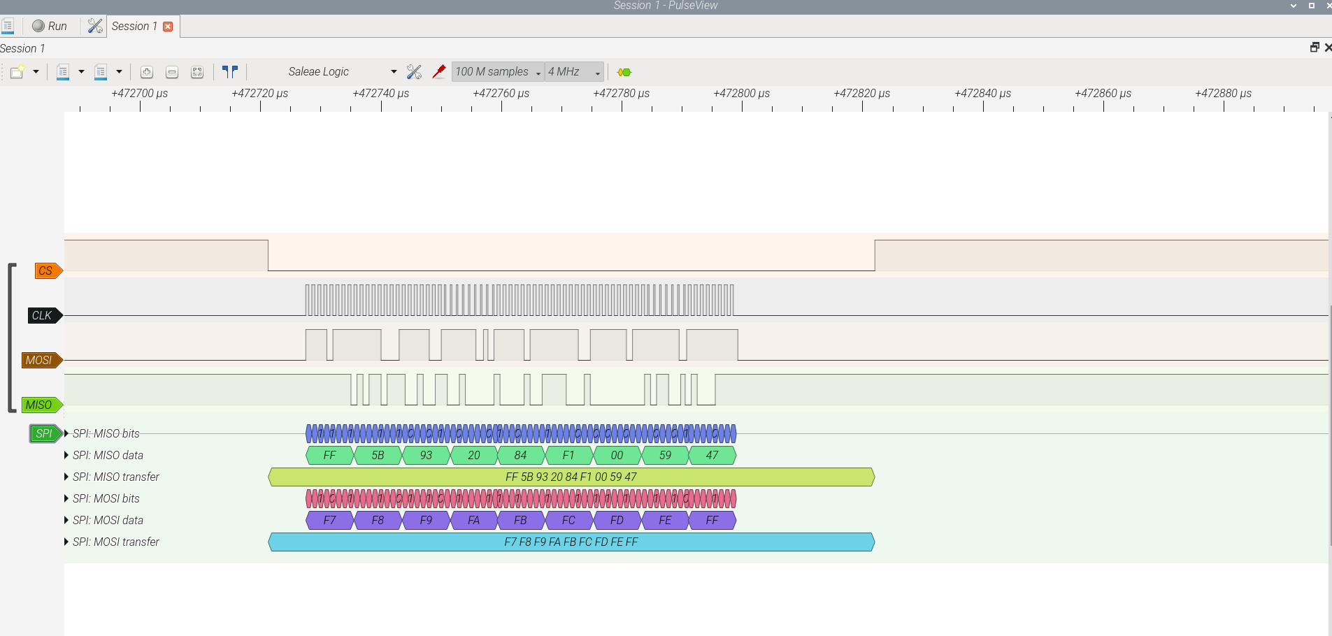
Here is a closer look at one of the 4 wire SPI interface messages (PRESSMSB, PRESSLSB, PRESSXLSB, TEMPMSB, TEMPLSB, TEMPXLSB, HUMMSB, HUMLSB, DUMMY) 9 Bytes being queried once per second by the Nordic nRF54L15-DK development kit running the Zephyr application located at the addresses,
#define PRESSMSB		0xF7
#define PRESSLSB		0xF8
#define PRESSXLSB		0xF9
#define TEMPMSB			0xFA
#define TEMPLSB			0xFB
#define TEMPXLSB		0xFC
#define HUMMSB			0xFD
#define HUMLSB			0xFE
#define DUMMY			0xFF
clearly seen in the MOSI line and the corresponding bytes received via the MISO line,
The Nordic nRF54L15-DK development kit can be used for many wireless IoT weather station projects where demanding power source constraints are present. The Nordic Power Profiler previously described in this article

can be used to characterize the power consumption of the device. The nRF52L15 IC is available from DigiKey. This Zephyr IoT weather station information can be interfaced to many displays that DigiKey have available if needed. One display example is the very inexpensive old time classic that can be interfaced via SPI or I2C,

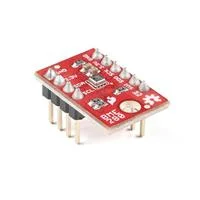
beside other options that has different display characteristics available from DigiKey. The Bosch BME 280 sensor is available in additional developement kits from Digikey such as the Sparkfun BME280,
Other additional weather sensors can be included in this Zephyr IoT weather station such as the Adafruit wind speed sensor to be preconditioned via the nRF52L15 SAADC interface (The voltage will range from 0.4V (0 m/s wind) up to 2.0V (for 32.4m/s wind speed). (See previous Zephyr SAADC article) available from Digikey.

There are newer Bosch sensors available from DigiKey that can be interfaced to this Zephyr IoT weather station such as the BME688,

Digital low power gas, pressure, temperature & humidity sensor with AI.
This particular sensor BME688 has more capabilities and applications such as,
- Indoor air quality measurement
- Bad breath or spoiled food detection based on the measurement of volatile sulfur compounds, which are an indicator of bacteria growth
- Detection of unusual gases and smells, which might indicate for instance a leakage
- Diaper state detection, e.g. for baby care
- Early detection of odors & bad smells
Please follow the Bosch BME 280 sensor manufacturer recommendations and guidelines for the required reflow process, mounting this sensor in a PC board properly since this can cause deviations from the expected measurements among other considerations.
Have a nice day!
Este articulo esta disponible en español aqui.
This article is available in spanish here.