I am testing a pulsed laser diode (SCW 1637-250R) using TI LMG1020EVM driver board to generate short pulse width for laser diode.
I put this laser diode on LMG1020EVM board and applied Vbus from 1V and increased this voltage slowly up to 12V. But I don’t see any voltage changes at Cathode node of laser diode and also current changes (0A) from the DC power supply generator for Vbus voltage (The max current limit in power supply generator is set to 1A for Vbus voltage).
Since this laser diode operating 1625nm of wavelength, we used ThorLabs VIS/IR Detector card to see the laser light visually, but no light is shown in the Detector card.
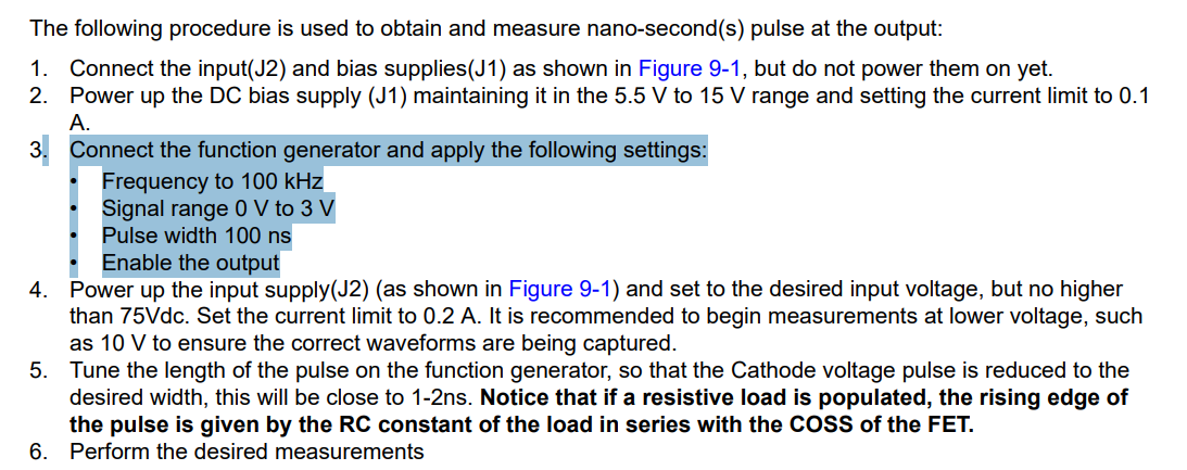
The input signal to the gate of GaN FET (EPC2019) inside of LMG1020 chip has 5.5V, 20n sec of pulse width, 1u sec of repetition rate.
Can you know how I can make this SCW 1637-250R laser diode operate with TI LMG1020EVM board?
Here are some images from our test setup.
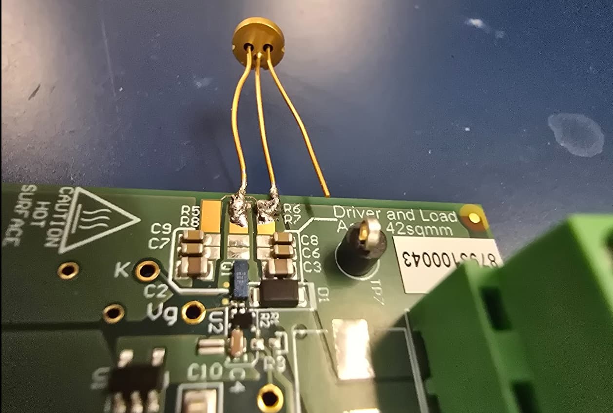
- LMG1020 EVM board with SCW 1637-250R - Anode and Cathode are connected as LMG1020EVM manual suggested.
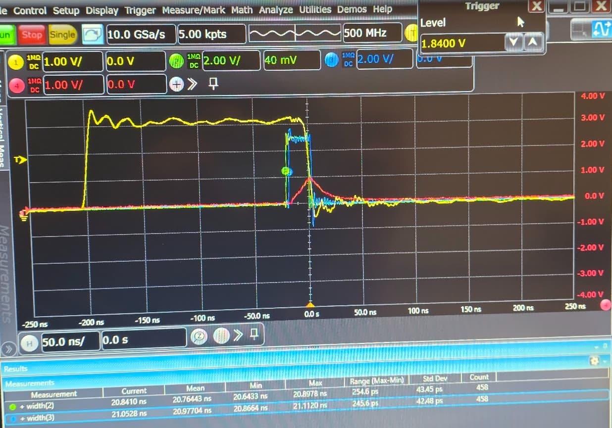
- Yellow waveform: Input signal from arbitrary signal generator to LMG1020EVM board
Green waveform: IN+ voltage on LMG1020EVM (5.5V, 20n sec of pulse width, 1u sec of repetition rate)
Blue waveform: Vg on LMG1020EVM (gate voltage to GaN FET of LMG1020)
(please ignore the red waveform)
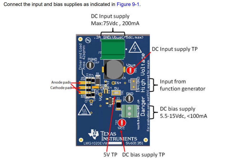
In the photos provided, I do not see that the function generator is connected. The J3 connections are open. The DC bias supply should have just the 5.5-15Vdc on it and be limited to 100mA.
The datasheet also notes the settings for the function generator for testing.
Hello,
Previous image was not showing J3 connections but testing was performed with all wires (J1~J3) connected.
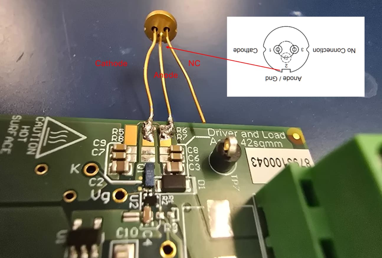
FYI, Below image is showing the connection between Laser diode (SCW 1637-250R) and LMG1020EVM. The node information of Laser diode is captured from its datasheet.
Can you please provide any comments to make this laser diode operate?
The blue trace would appear to indicate that gate drive pulse (TP4) is present, so some possibilities for the apparent lack of function might include:
- Gate signal not reaching the FET (bad PCB assembly)
- FET not reacting to gate pulse (bad/damaged FET)
- Laser voltage source not present (bad test leads aren’t uncommon)
- Bad connections of power supply/laser/eval board (solder joint by R6/R7 looks questionable)
- Bad/damaged laser
Also, the long leads on the laser are going to add some inductance to the system and slow current rise times compared to if the lead length was minimized.
Hello all,
I finally fixed this laser diode operation. It is working now by switching pin3 and pin1 of laser diode connection to the driver board. It would be better that datasheet can note that image of connections are top view or bottom view of laser diode.
Thank you for all about your comments.