Code Download
Version 1.1: pmod_ultrasonic_range_finder.vhd (3.6 KB)
Eliminated some synthesis warnings, no functional difference from v1.0
Version 1.0: pmod_ultrasonic_range_finder_v1_0.vhd (3.2 KB)
Initial Public Release
Features
- VHDL source code of a streamlined interface to Digilent’s Ultrasonic Range Finder (MAXSONAR) Pmod
- Continually outputs latest distance data on a parallel interface
- Handles all data retrieval from the MAXSONAR Pmod
- Converts received data to inches
- Configurable system clock rate
Introduction
This details a VHDL component that handles interfacing FPGAs to Digilent’s Ultrasonic Range Finder (URF) Pmod, shown in Figure 1. Figure 2 illustrates a typical example of this URF Pmod Interface component integrated into a system. As shown, the URF Pmod Interface connects to the Pmod’s pulse width (PW) port to gather distance information. It calculates the distance in inches and then presents it on a simple parallel interface, which can be connected to user logic or to output ports on the FPGA.

Figure 1. Digilent Ultrasonic Range Finder Pmod

Figure 2. Example Implementation
Background
The Ultrasonic Range Finder Pmod uses a Maxbotix ultrasonic sensor MB1010 LV-MAXSONAR-EZ1 to measure distance. The sensor has 3 outputs that each convey the same distance information: an analog voltage, a pulse width, and a UART. This FPGA interface design uses the pulse width, as it requires the least FPGA resources to implement. The pulse width output is simply a variable width pulse, whose duration corresponds to the distance of the object detected.
Theory of Operation
Following a 350ms startup delay, the URF Pmod sends a pulse on its the pulse width (PW) output every 49ms. The width (duration) of this pulse ranges 0.88ms ≤ PW ≤ 37.5ms. Each 147us represents one inch to the detected object.
The URF Pmod Interface logic uses two counters to evaluate the distance. When the PW signal is asserted, the first counter counts system clock pulses until it reaches the equivalent of 147us. At this point, it clears, and the second counter increments to log the inch. This process repeats until the PW signal deasserts.
Once the PW signal deasserts, the value of the 2nd counter (i.e. the total number of inches) is typecast to a standard logic vector and output on the distance port as a binary number. Both counters are cleared to prepare for the next measurement.
Configuring the Clock
The clocking of this URF Pmod Interface is configured by assigning a value to the GENERIC clk_freq, defined in the ENTITY. This generic must be set to the provided system clock’s frequency in MHz.
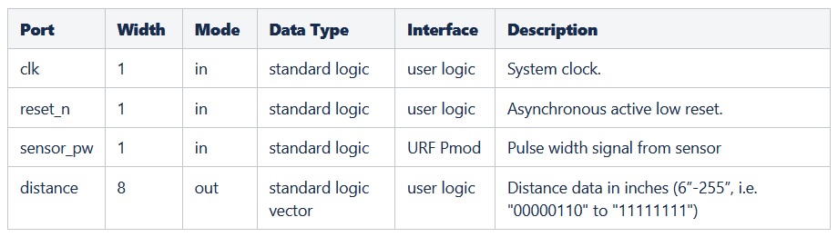
Port Descriptions
Table 1 describes the URF Pmod Interface’s ports.
Table 1. Port Descriptions
Connections
This Pmod has a 6-pin connector. Table 2 provides the pinout for this connector. The URF Pmod Interface code’s ports need to be assigned to the FPGA pins that are routed to this connector as listed.
Table 2. URF Pmod Pinout and Connection to the FPGA’s URF Pmod Interface Component

Reset
The reset_n input port must have a logic high for the URF Pmod Interface to operate. A low logic level on this port asynchronously resets the component. During reset, the component aborts the current reading and ignores the URF Pmod input. It also clears the distance output and its internal logic. Once released from reset, the URF Pmod Interface resumes operation.
Conclusion
This URF Pmod Interface is a programmable logic component that interfaces to Digilent’s Ultrasonic Range Finder Pmod. It handles all communication with the URF Pmod to provide a continual stream of updated distance data on a parallel output.