Three types of files are associated with IO-Link including:
-
GSDML File for the IO-Link master. Without this file the IO-Link master does not exist from the PLC’s perspective.
-
IODD file for individual field devices. Without these files, the IO-Link master is an expensive digital IO device with no IO-Link capabilities.
-
Device specific function blocks for the PLC (optional). Without these, you have a mountain of programming and debugging.
At a Glance
-
The IO-Link master is a bidirectional bridge that speaks PROFINET on one side and IO-Link on the other.
-
The PLC never sees ports, it sees PNIO submodules.
-
The IO-Link master never sees hardware, it sees IO-Link data.
-
IO-Link’s configuration may be split between the PLC and IO-Link master.
This article is part of the DigiKey Field Guide for Industrial Automation
Location: Program It → Networks & Protocols
Difficulty: ![]() Engineer — difficulty levels explained
Engineer — difficulty levels explained
Author: Aaron Dahlen | MSEE | Senior Applications Engineer, DigiKey
Last update: 06 Mar 2026
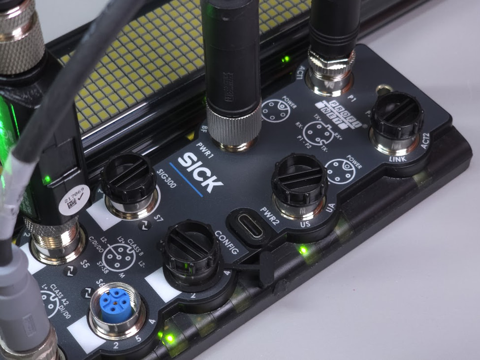
Figure 1: Image of a SICK SIG300 IO-Link master.
What is the purpose of the GSDML File?
-
The GSDML file is read by TIA Portal and serves as a menu-driven tool that you use to configure the IO-Link master.
-
The GSDML file is provided by the manufacturer of the IO-Link master. In this example, SICK provides the file for the SIG300 (Figure 1).
Tech Tip: Technically, the GSDML file is not part of the IEC 61131-9 IO-Link standard. Stated another way, the PLC never speaks IO-Link directly. For example, the PLC communicates with the SICK master shown in Figure 1 using PROFINET as defined by IEC 61158 and IEC 61784.
How to Conceptualize the GSDML File
The GSDML file describes the available building blocks (modules and submodules) exposed to the PLC. It’s the OEM’s description of what your PLC can do with the IO-Link master and ports. For example, let’s install an IO-Link distance sensor on port S4.
-
The port must be configured to match the sensor including the memory requirements identified in the OEM’s data e.g., a 32I / 32O interface.
-
TIA Portal assigns the memory locations and the programmer links these locations to PLC tags
Rack and Slot Analogy
Think of the IO-Link master in terms of rack and slot. Conceptually, we have a PROFINET-ready rack with a backplane to accept cards. Nothing happens unless the rack and cards are properly configured.
-
The body of the IO-Link master is the rack.
-
Each M12 port is a software interface waiting to be instantiated in the PLC configuration.
An uninstantiated port is deactivated by default as if the physical card were never installed.
Tech Tip: The GSDML makes sense if we stand within the TIA Portal environment and direct our attention to the IO-Link devices. This framing is essential to understanding IO-Link. Without it, we conflate hardware with software, leading to incorrect assumptions on the nature of IO-Link.
Figure 2 shows the configuration for the SIG300. The right-hand side presents the SIG300 options exposed to the PLC. The device overview describes the actual interface for the SIG300. The type column shows the actual port configuration such as digital output or IO-Link 32I/32O. Without the GSDML file there would be no right-hand submodules.
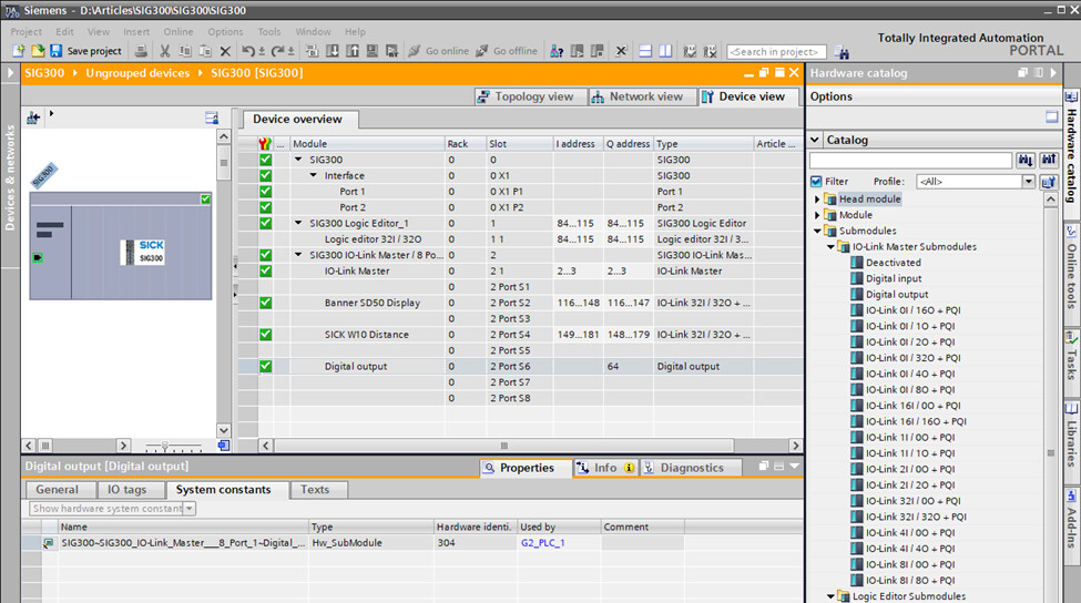
Figure 2: Instantiation of the SIG300 ports.
Clarification on Cyclic and Acyclic Communication
There are two ways for the PLC to interface with IO-Link devices:
-
Cyclic: This is the preferred method as it is automatically performed as part of routine PROFINET I/O (PNIO) operations. From a programmer’s perspective, cyclic operations are no different than any other digital or analog module attached to the PLC. Configure the device once and then use the tags as part of the larger program. The update time can be adjusted to balance freshness against network bandwidth.
-
Acyclic: The acyclic operations are still part of PNIO exchange. However, they are activated as required. This can be part of a startup routine or as needed in your program.
This is an important consideration for the GSDML. The device overview (Figure 2) identifies instantiated cyclic PNIO ports. This allows you, the programmer, to configure the IO-Link submodule once and then use it as if it were part of the PLC’s local IO.
Tech Tip: The user main [OB1] program does not control the PNIO. It’s possible for PNIO to perform many updates while OB1 is chewing on a large program. This distinction is especially important when we transition to time-critical messaging such as PROFIsafe.
What is the purpose of the IODD File?
-
The IODD file is imported into the IO-Link master where it is used as a roadmap describing the field device connected to the port. The IODD file may be retrieved from the field device itself, downloaded from the OEM webpages, or from IO-Link.
-
The IODD file is provided by the manufacturer of the individual field devices such as the SICK W10 distance sensor shown in Figure 3.
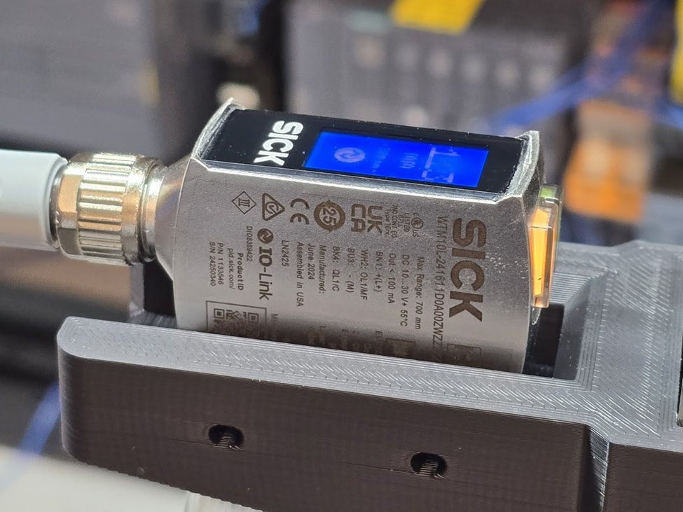
Figure 3: Image of the SICK W10 IO-Link equipped distance sensor.
How to Conceptualize the IODD File
While the sensor features a microcontroller, the IODD should not be confused with a register map.
The IODD describes the interface between the IO-Link master and the field device using the IEC 61131-9 protocol. Like the GSDML file, the IODD describes the exposed features. For example, the SICK W10 shown in Figure 3 contains a microcontroller that communicates using the single-wire bidirectional interface. The IODD file describes the configuration parameters and data that is shared across the physical (M12) connection.
How to Conceptualize the GSDML and IODD Relationship
Think of this as a two-stage mapping operation.
- The PLC speaks in terms of tags and memory locations
- The GSDML file is necessary to map tags to cyclic PNIO submodules
- The IO-Link master bridges PNIO (Ethernet) to IO-Link (serial)
- The IODD file is necessary to map IO-Link to master data to the field device
- The end of the line field devices provide data or act on provided data
What is included in the IODD file?
Without the IODD file the IO-Link master becomes an expensive multiport digital IO module. This backwards-compatible interface is configured and controlled using the TIA Portal tools shown in Figure 2. This assumes the GSDML file is properly loaded into TIA Portal.
The IODD file is required to unlock the IO-Link functionality for an IO-Link equipped field device. It does so on a port by port basis where a specific IODD file is required to match the singular field device connected to the physical port. What was limited to primitive IO becomes a smart sensor interface.
As an example, consider the Figure 4 IODD Viewer for the SICK W10 sensor. Note that we are logged into the USB service port of the device.
The SIG300 web server has built this entire page based on:
-
The sensor description contained within the IODD file.
-
The real-time data retrieved from the W10 sensor.
Consider the Distance to Object field (last field in the center column). The IODD file effectively told the SIG300 that this field existed. The SIG300 then pulled data from the sensor and populated the field. The SIG300 also makes this data available to the PLC via the PNIO submodule associated with port 4.
Tech Tip: Consult the field device literature to determine the memory size of the cyclic data. This essential thread runs from PLC to IO-Link master to field device to ensure that the data arrives quickly and fully intact for use by the PLC or vice versa.
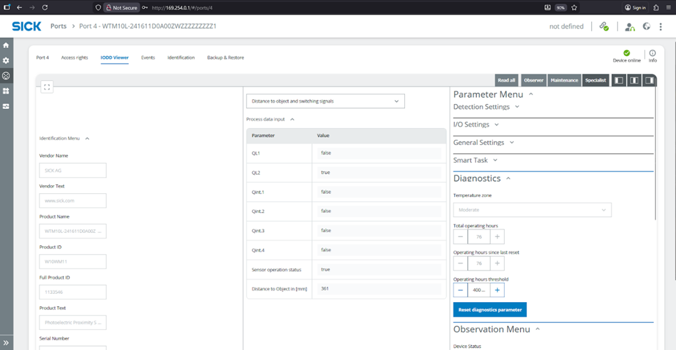
Figure 4: Data from the SICK IODD Viewer for the W10 distance sensor.
Exploring the IODD file
We can examine the IODD file to find identification data for the sensor; the answer is somewhere in those angle brackets. Here is an example for some of the obvious SICK W10 fields. We will leave discovery of the cyclic and acyclic data bins for another day. This is one of those applications where AI can help discover and understand the file structure. Then again, the OEM’s tools (Figure 4) are much easier to use.
<DeviceIdentity deviceId="8389422" vendorId="26" vendorName="SICK AG">
...
...
<DeviceVariant deviceIcon="SICK-W10-icon.png" deviceSymbol="SICK-W10-pic.png" productId="W10WM11">
Tech Tip: The IO Device Description (IODD) is IO-Link master centric. We now position ourselves into the configuration environment of the IO-Link master. The IODD tells us what field device options have been exposed to the IO-Link master. The IO-Link master then makes the fields available as PNIO submodules for the PLC for both cyclic and acyclic interface.
How to conceptualize the OEM provided library
Many OEM’s provide PLC libraries for the field devices. This includes function blocks and data types to simplify the PLC programming. This is not always necessary but is extremely helpful especially when it comes to configuring an IO-Link device.
Some applications do not need libraries such as the SICK W10 distance data which is available out-of-the-box in the cyclic form. However, the configuration settings are more complex. For instance, these IODD lines are associated with using the M12 connector pin 2 as an output.
<Text id="TI_85" value="Physical input / output type configuration pin2"/>
<Text id="TI_86" value="PNP"/>
<Text id="TI_87" value="NPN"/>
<Text id="TI_88" value="Push/Pull"/>
A SICK to PLC library is highly desirable to set these memory locations. Alternatively, they may be set using the SICK IO-Link master graphical tools (Figure 4). However, this requires considerable attention as the “IO-Link” truth is now split between the PLC and IO-Link master. Ideally, the program would be held in the PLC as a single point of control. This golden truth also simplifies version control as only one backup is required as opposed to splitting authority.
Tech Tip: OEM provided libraries may or may not be acyclic even though they appear in OB1 or other blocks. For simplicity, we may use a library to set or get data from the I and Q addresses identified in Figure 2.
Parting Thoughts
Watch out! The phrase “IO-Link truth is now split between the PLC and IO-Link master” has terrible implication to future maintenance technicians. It means that IO-Link configurations and version control can fall through the cracks. The hazard occurs when the IO-Link master fails.
Go look. Where are your IO-Link master configuration files?
Don’t start looking at 3 AM.
Best wishes,
APDahlen
 Continue Exploring Industrial Control Systems
If this discussion was helpful, you may also want to explore:
 DigiKey Navigation
- Full Catalog: Industrial Control & Automation
 Related Foundational Articles
- Thermal PID on the Siemens S7 PLC
- Emulating Enumerated States in Siemens PLCs for Module-to-Module State Transfer
- How to Clear PLC to SICK SIG300 Errors
About This Author
Aaron Dahlen, LCDR USCG (Ret.), is a Senior Applications Engineer at DigiKey in Thief River Falls. His background in electronics and industrial automation was shaped by a 27-year military career as both technician and engineer, followed by over a decade of teaching.
Dahlen holds an MSEE from Minnesota State University, Mankato. He has taught in an ABET-accredited electrical engineering program, served as coordinator of an electronic engineering technology program, and instructed military technicians in component-level repair.
Today, he has returned to his home in northern Minnesota, completing a decades-long journey that began with a search for capacitors. Read his story here.