Configure a PID on a Siemens PLC using the PID_Temp Technical Object (TO). The physical plant consists of a LM335 sensor and a 1 kΩ resistor as a heater. Focus on plant construction, PLC programming, auto tuning, and results of the plant’s response to a step change.
Key Takeaways
- Project Demonstrated on a Siemens Gen 2 CPU 1214C (Figure 1)
- Analog plug-in module 6ES7 233-4HD50-0XB0
- PID contained within a cyclic interrupt running once a second
- PID control using the PID_Temp Technical Object (TO)
- 10 Hz PWM (without TO) on Local DC/DC/DC output pin Q0.0 (24 VDC supplied to the load)
- Feedback via an LM335 temperature sensor (10 mv/K) read by the analog plug-in module
This article is part of the DigiKey Field Guide for Industrial Automation
Location: Program It → PID & Analog
Difficulty: ![]() Engineer — difficulty levels explained
Engineer — difficulty levels explained
Author: Aaron Dahlen | MSEE | Senior Applications Engineer, DigiKey
Last update: 06 Mar 2026
Prerequisite Reading
This is intermediate level material. At this point, you need to know TIA Portal, LD/ST, and HMI operation. Also, review these prerequisite articles:
-
Analog input and scaling: Configure the Siemens analog modules and scaling of raw ADV values into a human readable format.
-
PWM Configuration: Configure the PWM on a S7 DC/DC/DC CPU.
-
PID Overview and PID Thermal Example: PID theory with examples including a motor and a thermal system.

Figure 1: PID project on the author’s workbench showing PLC, HMI, and the heater / sensor installed on a breadboard.
Introduction
PID control is so common in industrial automation that Siemens includes it as a built-in Technical Object (PID_Temp) in TIA Portal. This saves time, especially with automatic tuning. But don’t get too comfortable, as you still need the prerequisite lessons to troubleshoot the system when things go wrong.
Figure 1 shows the project on the workbench. The LM335 temperature sensor and 1 kΩ resistive heater simulate a larger industrial system. Our mini plant operates at 25 VDC and has a fast time constant. It’s more convenient than a real world system such as a 1000 gallon tank with a heater controlled by a three-phase 460 VAC SCR chopper.
Project Construction
The thermal plant is shown in Figure 2, where we see the 1 kΩ heater tie wrapped to the LM335 sensor. The 15 kΩ biasing resistor is seen in the background. The accompanying wire diagram is shown in Figure 3.

Figure 2: Image of the thermal system with heater tie wrapped to the temperature sensor.
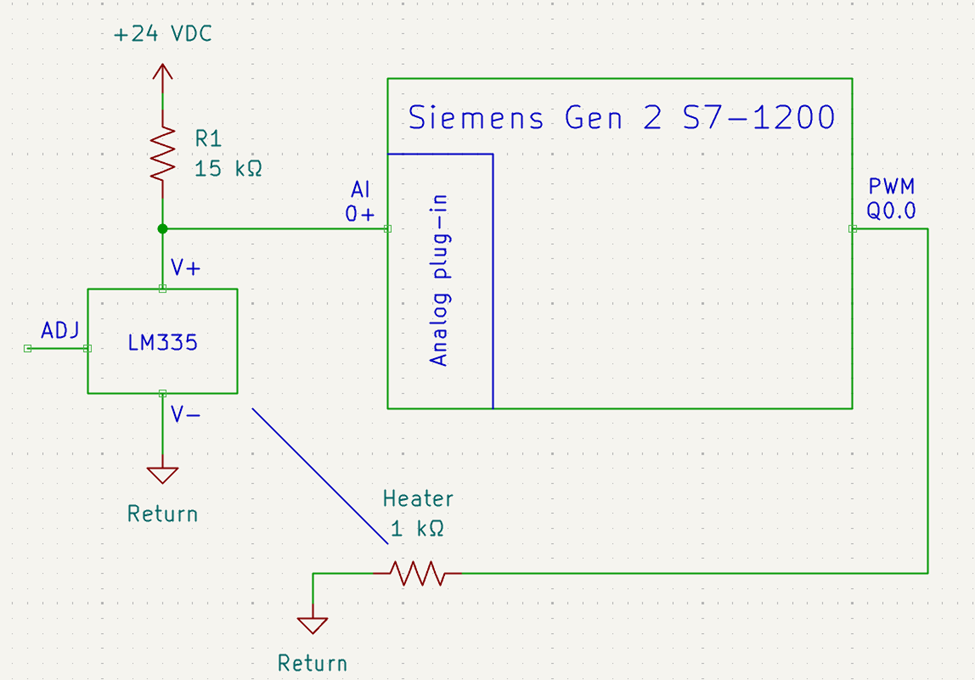
Figure 3: Wire diagram for the PLC-based thermal system.
Programming
The Siemens PID_Temp technical object handles the classic analog PID routines. However, it does need a few rungs of helper code.
Scale the Input
Figure 4 presents the analog scaling blocks which are used to convert the raw LM335 sensor data into a human readable Fahrenheit value.
-
The raw ADC value is converted to its equivalent voltage where the ADC value 0227,648 maps to 5.0 VDC.
-
The voltage held in rScratch is then converted to a Fahrenheit temperature. Knowing that the LM335 is configured for 10 mV/K we use a convenient number scaling from absolute zero to boiling water where 0 to 3.7315 maps to -459.67 to 212.0.
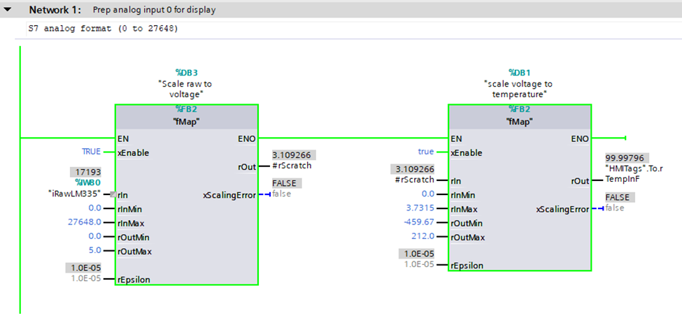
Figure 4: Scale the LM335 temperature sensor to a voltage and to the Fahrenheit equivalent.
Tech Tip: Figure 4 breaks the scaling into two steps. It first converts the raw ADC to a voltage (rScratch) then it performs a second conversion to Fahrenheit. This intermediate value is useful for development and troubleshooting. For example, the rScratch value will match the value measured via a multimeter placed on the sensor’s terminals.
You decide if readability and easy troubleshooting are with the extra memory usage and the slightly reduced loop speed.
Set the PWM
The PID_Temp technical object is shown in Figure 5. The operator sets the setpoint in the HMI and the feedback (input) is the scaled LM335 temperature in Fahrenheit. The OutputHeat value is sent to a scaling block which maps the percent drive to the S7 analog format used to drive the PWM. The 0 to 100.0 percent maps to 0 to 27,648.
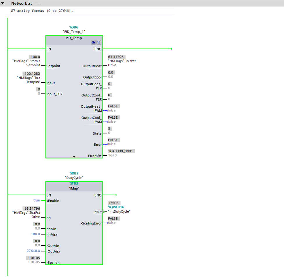
Figure 5: Ladder logic code including the PID_Temp technical object and output scaling block.
Automatic Tuning
Click on the PID_Temp commissioning icon (screw driver plus pliers icon) to open the PID tuning tools. Here are the important sections:
-
Measurement panel (Figure 6): This is used to set the sampling and start the waveform viewer. There is also a pushbutton to activate the automatic tuning.
-
Tuning Status (Figure 7): The PID controller has two inputs (setpoint and feedback) and two outputs showing the percent drive for the heating and cooling mechanisms. A progress indicator shows the status of the auto tuning. It also has a few controls allowing on-the-fly change of setpoint and an override for the plant’s percent duty cycle output.
-
Waveform display (Figure 8): The waveform display is used to visualize the plant’s operation. This includes setpoint, feedback, and the percent drive for heating and cooling.

Figure 6: Master control panel for the PID_Temp technical object.
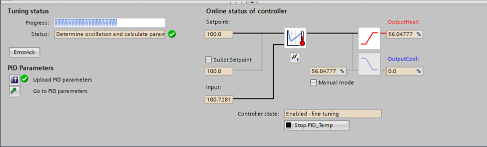
Figure 7: Control panel for the PID_Temp technical object shown in the automatic tuning process.
Tech Tip: The Siemens PID technical object can control both heating and cooling via independent PLC outputs. For example, it could heat a system using a three-phase SCR chopper and cooling via proportioning valve to route the fluid to a cooling loop.

Figure 8: Waveforms associated with an automatic tuning cycle from minute 3 to minute 16.
Tech Tip: Don’t forget to upload the PID parameters to the PLC when the tuning is completed. This is done by clicking on the button in the lower left hand corner (Figure 7). Failure to upload will result in lost time as the tuning process takes a considerable amount of time especially for large systems with long time constants.
Additional Resources
Refer to the Siemens literature for detailed information about the PID technical objects. The document includes instructions for PID setup and configuration. It also includes implementation and optimization tips.
Read your textbook or ask a chatbot for additional information about PID operation. Be ready to define words such as time constant, overshoot, oscillation, steady state error, integral windup, and gain scheduling. You need this vocabulary to commission a PID. It’s also likely to be included in a job interview.
Results
The results of the tuned system are included as Figure 9 with the setpoint shown in black and the actual temperature in blue. There are multiple steps including jumps from 100° to 90° to 110° and then back to 90° Fahrenheit.
Observe:
-
Figure 9 is a close up of the right-hand-side data from Figure 8.
-
The plant has an asymmetric response with a fast (active) heating response and a slower (passive) cooling response.
-
Steady state error within a ± 1° Fahrenheit envelop.
-
Refer to Figure 8 to see the corresponding drive signal (red).

Figure 9: Response of the system to a step change.
Parting Thoughts
The Siemens PLC was easy to use with near single click operation. In fact, configuring the ADC and PWM was the hardest part of this project.
However, if I were your teacher, I would insist that you roll your own as described in the prerequisite articles. You need the school of hard knocks to truly understand the impact of the tuning parameters. As a compromise you could manually tune the PID using the controls shown in Figure 10. In this case, I’ve manually set the gain to 100.0 causing the system to oscillate.
Happy tuning,
APDahlen
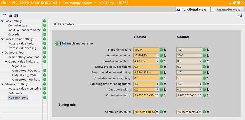
Figure 10: PID tuning parameters with the proportional gain manually forced to 100.0.
 Continue Exploring Industrial Control Systems
If this discussion was helpful, you may also want to explore:
 DigiKey Navigation
- Full Catalog: Industrial Control & Automation
 Related Foundational Articles
- Getting Started with the Siemens ET 200SP Distributed I/O
- Getting Started with the Siemens Safety PLC
- Use of an Interposing Relay for Increased Contactor Speed
About This Author
Aaron Dahlen, LCDR USCG (Ret.), is a Senior Applications Engineer at DigiKey in Thief River Falls. His background in electronics and industrial automation was shaped by a 27-year military career as both technician and engineer, followed by over a decade of teaching.
Dahlen holds an MSEE from Minnesota State University, Mankato. He has taught in an ABET-accredited electrical engineering program, served as coordinator of an electronic engineering technology program, and instructed military technicians in component-level repair.
Today, he has returned to his home in northern Minnesota, completing a decades-long journey that began with a search for capacitors. Read his story here.