Pulse Width Modulation is an option for PLCs with solid-state outputs like the Siemens Gen 2 CPU 1214C shown in Figure 1. This procedural engineering brief shows how to configure the PLC’s PWM output with additional tips for scaling the values and using the Siemens S7 analog format where analog values are represented as an integer between -27,648 and 27,648.
At a Glance (Test Configuration)
- CPU: S7-1200 CPU 1214C (Gen 2) using TIA Portal v20
- Direct pulse generator control. No Siemens Technical Objects (TO) were used.
- Pulse generator name: Pulse_1
- Time base: 100 ms period (10 Hz)
- Output pin: Local DC/DC/DC output pin located at Q0.0 (24 VDC supplied to the load)
- Duty write address: %QW1016 using S7 Analog format (unipolar 0…27648)
- Duty example: variable 0 to 100 %, but you will need to add sanity block
- Update task: Cyclic interrupt OB30 (e.g., 1 s)
This article is part of the DigiKey Field Guide for Industrial Automation
Location: Program It → PID & Analog
Difficulty: ![]() Engineer — difficulty levels explained
Engineer — difficulty levels explained
Author: Aaron Dahlen | MSEE | Senior Applications Engineer, DigiKey
Last update: 06 Mar 2026

Figure 1: Image of a Siemens 2nd-generation S7-1200 CPU 1214C on a Phase Dock trainer.
Tech Tip: The PWM output is available on DC/DC/DC designated PLCs. In this case, we have a PLC with 24 VDC power supply requirements, DC inputs, and solid-state outputs.
The PWM is not available on a DC/DC/Relay type PLC. We can always expand the PLC to include PWM using a plug-in module, expansion module, or distributed I/O using the ET 200SP family.
Steps to Activate the S7-1200 PWM
Setting up an S7-1200 PWM is a multi-step process.
Configure the Hardware
The first step is to configure the S7-1200 hardware-based pulse generator. This is done in the hardware configuration section as shown in Figure 2.
-
Enable the pulse generator.
-
Give it a name: Pulse_1.
-
Set PWM mode including the desired time base, period, and input format. We use the S7 analog format as described in the next tech tip.
-
Select runtime modification of the duty cycle for on-the-fly PWM adjustment.
-
Output the PWM to the desired pin: Q0.0.
-
Remember the start address for the PWM as it will be used to set the duty cycle. In this example the address is %QW1016.

Figure 2: Hardware configuration for the PWM.
Tech Tip: Siemens programmers often use the “S7 analog format.” By definition, the values range from -27,648 to 27,648. For example, a 0 to 20 mA current input would map to 0 to 27,648 while a -10 to 10 VDC input would scale between -27,648 and 27,648. Click here for additional information about normalizing and scaling data.
Compile and then Download the Hardware Changes
Update the hardware by first compiling as shown in Figure 3. Then select “download to device” to apply the changes to the PLC.
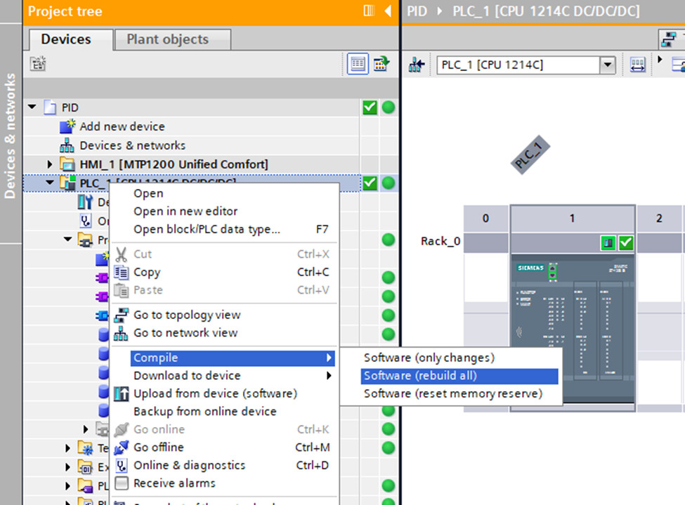
Figure 3: Location of the PLC hardware compilation instruction in TIA Portal.
Assign a Tag Name
Assign a memorable tag name to the PWM memory address. For example, I instantiated a PWM tag table and then mapped tag intDutyCycle to memory location %QW1016.
Activate the PWM in Your Code
The CTRL_PWM function block shown in Figure 4 is required to activate the hardware pulse generator. In this example, the PWM is enabled via a selector switch. Note that CTRL_PWM is part of Siemens function library (verified in V20).

Figure 4: The control PWM block will activate the pulse generator.
Scale and then Write the Desired Duty Cycle
The PWM duty cycle may be changed on-the-fly by writing to the memory location previously identified as intDutyCycle (%QW1016) as shown in Figure 5.
- Top rung: Forces the duty cycle to zero unless the selector switch (SW1) is active.
- Mapping rung: A floating point mapping function block (referred to as fMap) used to scale the percent duty cycle to the Siemens S7 analog format. In this case 0.0 to 100.0 is mapped to 0 to 27,648. You can copy the code into TIA Portal.
The mapping code is included as Listing 1. It’s ready to paste provided you first add the I/O and memory interface to a new function block The resulting block is typically included in a cyclical-interrupt OB. For example, a thermal PID may update the PWM once a second (article coming soon).

Figure 5: Write a new duty cycle to the PWM pulse generator. Note that an implicit cast is used to convert a real to an int.
(*
 * FUNCTION_BLOCK fMap (Floating-Point Mapping)
 * DESCRIPTION:
 *   Scales an input value linearly from [rInMin, rInMax] to [rOutMin, rOutMax].
 *   Supports reversed ranges (negative slope) and allows extrapolation
 *   beyond input limits. When xEnable = FALSE or spans are invalid
 *   (|span| ≤ rEpsilon), the block holds the last valid output.
 *
 * NOTE:
 *   Siemens ADC full-scale values:
 *      - Current inputs (0 to 20mA):  0 to 27,648
 *      - Voltage inputs (-10 to 10 VDC): -27,648 to +27,648
 *   Ref: https://support.industry.siemens.com/cs/mdm/109741593
 *
 * TODO:
 *   1) Add complementary alarm unit for min/max warnings and limits.
 *   2) Implement a saturation (clamp) block to constrain I/O values.
 *   3) Replace "magic numbers" (e.g., 5530 for 4–20 mA lower bound)
 *      with named constants.
 *
 * INPUTS:
 *   #xEnable      : BOOL   → FALSE holds last valid output
 *   #rEpsilon     : REAL   → Small span guard, recommended 1e-5
 *   #rIn          : REAL   → Input value (raw or normalized)
 *   #rInMin       : REAL   → Lower input limit
 *   #rInMax       : REAL   → Upper input limit
 *   #rOutMin      : REAL   → Lower output limit
 *   #rOutMax      : REAL   → Upper output limit
 *
 * OUTPUTS:
 *   #rOut         : REAL   → Scaled output or last valid value
 *   #xScalingError: BOOL   → TRUE when spans invalid (|span| ≤ rEpsilon)
 *
 * INTERNAL VARIABLES:
 *   (Retained between scans)
 *   #rInSpan   : REAL  // Input span
 *   #rOutSpan  : REAL  // Output span
 *   #rGain     : REAL  // Calculated slope
 *   #rLastOut  : REAL  // Retained last valid output
 *
 * Header written with assistance from GPT 5o
*)

IF NOT #xEnable THEN
    #rOut := #rLastOut;
    RETURN;
END_IF;

#rInSpan := (#rInMax - #rInMin);
#rOutSpan := (#rOutMax - #rOutMin);

IF (ABS(#rInSpan) > #rEpsilon)   // Only scale if the in and out spans are meaningful.
    AND (ABS(#rOutSpan) > #rEpsilon) THEN

    #rGain := #rOutSpan / #rInSpan;
    #rOut := ((#rIn - #rInMin) * #rGain) + #rOutMin;
    #rLastOut := #rOut;
    #xScalingError := FALSE;

ELSE
    #rOut := #rLastOut;
    #xScalingError := TRUE;
END_IF;
Listing 1: A floating point map scaling block is used to convert the percent duty cycle to the S7 Analog format.
Tech Tip: The Listing 1 fMap function was inspired by the Arduino map function. Refer to this page to learn more about the linear scaling process. Note that the code is adapted to the PLC with additional functionality including the ability to hold the last number when not enabled. It also includes protection against small numbers close to zero with the epsilon lockout.
Results
The PLC’s output signal as measured by a Digilent ADP2230 is shown in Figure 6.
- The PLC is driving a 1 kΩ resistor (not shown and configured as sourcing).
- The output level toggles between 0 and approximately 24 VDC.
- The waveform has a 100 ms period (10 Hz). Recall that this was an adjustable field as shown in Figure 2.
- The duty cycle (on time) is approximately 24 %.

Figure 6: PLC’s PWM output waveform (driving a 1 kΩ resistor).
Tech Tip: Watch out for inductive kick! The solid-state outputs on the Siemens PLC are protected. However, it’s generally bad practice to depend on the internal protection to clamp the high voltage inductive spikes. This article shows how polarity protection is built into industrial relays while this article demonstrates the need for interposing relays when controlling larger motor starters.
Parting Thoughts
-
Stay tuned as the PWM will be used in a PID application to control a thermal system.
-
Break the code in the name of defensive programming. What is missing?
-
Don’t make your PLC eat the inductive spikes!
Best wishes,
APDahlen
 Continue Exploring Industrial Control Systems
If this discussion was helpful, you may also want to explore:
 DigiKey Navigation
- Full Catalog: Industrial Control & Automation
 Related Foundational Articles
- Getting Started with the Siemens ET 200SP Distributed I/O
- Getting Started with the Siemens Safety PLC
- Guide to Troubleshooting Industrial Control and Automation Equipment
About This Author
Aaron Dahlen, LCDR USCG (Ret.), is a Senior Applications Engineer at DigiKey in Thief River Falls. His background in electronics and industrial automation was shaped by a 27-year military career as both technician and engineer, followed by over a decade of teaching.
Dahlen holds an MSEE from Minnesota State University, Mankato. He has taught in an ABET-accredited electrical engineering program, served as coordinator of an electronic engineering technology program, and instructed military technicians in component-level repair.
Today, he has returned to his home in northern Minnesota, completing a decades-long journey that began with a search for capacitors. Read his story here.