This engineering brief introduces the Siemens ET 200SP distributed I/O system. The featured hardware is highly desirable for the classroom as it allows students to continue their exploration of the Siemens S7-1200 and S7-1500 PLC ecosystems. The core utility of the article is a series of lessons learned including hardware configuration, TIA Portal configuration, and programming tips to best utilize remote tags.
Familiarity with Siemens PLC and tag based variables is assumed.
This article is part of the DigiKey Field Guide for Industrial Automation
Location: Understand It → Network Fundamentals
Difficulty: ![]() Technician — difficulty levels explained
Technician — difficulty levels explained
Author: Aaron Dahlen | MSEE | Senior Applications Engineer, DigiKey
Last update: 06 Mar 2026
What is Distributed I/O?
Distributed I/O is an extension of the PLC. Recall that a PLC such as the Siemens S7-1200 features a variety of digital and analog inputs and outputs (I/O) along with other specialized hardware such as high-speed counters and pulse generators.
Traditionally, we think of the PLC as fixed with optional expansion modules clipped to the right-hand side of the PLC. The distributed I/O (remote I/O) takes this idea to the next level. Instead of expanding the local PLC, the distributed I/O may be installed in remote control panels with a high-speed network interface.
The integration software is the best part of the distributed I/O. Instead of viewing each control cabinet as a discrete entity, the remote I/O components are pulled into the PLC tag table as if they were native. With a bit of naming discipline, the remote hardware is as easy to use as the local PLC hardware.
Representative Example from the Author’s Workbench
A demonstration Siemens ET 200SP setup is shown in Figure 1. As configured, the modules provide 8 digital inputs and 16 digital outputs. A variety of support hardware is shown in the picture, including an electronic circuit breaker, relays, and pushbuttons all installed on an industrial breadboard
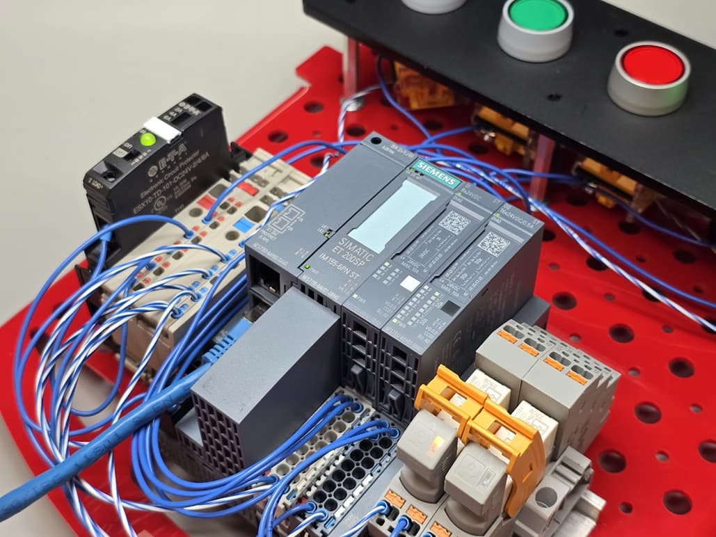
Figure 1: The Siemens Simatic ET 200SP installed on an industrial breadboard with supporting hardware.
Itemized list of the ET 200SP Hardware
For clarity we identify the ET 200SP hardware used in this experiment.
-
Interface module 6ES7 155-6AU01-0BN0 prominently displayed in the middle of Figure 1 with the pastel blue tag and distinctive SIEMENS logo.
-
PROFINET adapter 6ES7 193-6AR00-0AA0 mounted on the interface module. The RJ-45 connectors can be seen.
-
Digital input module (24 VDC with 8 inputs) 6ES7 131-6BF01-0BA0 plugs into the matching 6ES7 193-6BP00-0DA0 base unit.
-
Digital output module (24 VDC with 16 outputs) 6ES7 132-6BH01-0BA0 plugs into the matching 6ES7 193-6BP00-0BA0 base unit.
-
Server module 6ES7 193-6PA00-OAAO (VERSION 1.2)
Tech Tip: The server module clips to the far right-hand side of the assembly. It is just visible as a 3/8-inch sliver between the output module and the control relay. We are tempted to view this fuse holder module as an afterthought. However, when we open the unit up we see a relatively complicated circuit as shown in Figure 2.
Misconceptions: This was an important step in my learning as I had previously assumed the server module was a terminating resistor.

Figure 2: Teardown of the Siemens ET 200SP server module.
Lessons Learned: Hardware
The base units can be a point of confusion as they all look the same but provide different connections to the plug-in units.
If I were to teach this material today, I would give the students the disassembled component. This would allow them to understand the physical component relationships. It would also allow them to make natural mistakes such as using the incorrect base for each plug-in module. A more charitable exercise is to use the Siemens TIA portal Selection Tool to configure the distributed I/O. This tool clearly identifies the module part numbers including the base units.
As noted in the previous tech tip, be sure to clip the server module to the right-hand side of the unit.

Figure 3: Use of the Siemens TIA Selection tool to configure the ET 200SP distributed I/O. Server module not shown.
Lessons Learned: Software
One of the most challenging aspects is differentiating between a hardware and a software error. For example:
-
Installation of an incorrect base unit will show up as red failure in TIA Portal. My recommendation is to carefully compare the physical base unit part number with the TIA portal hardware configuration options. Stated another way, build the physical unit at the same time as you configure the TIA Portal representation. Careful mirror the base unit for the chosen plug-in module.
-
Selecting an incorrect server module version number will cause a red failure in TIA Portal. Like the base module selection, this is an important part of mirroring the TIA Portal to the physical hardware. I had to take the server module apart before this registered (see the previous Tech Tip).
-
Incorrect port assignments will prevent the PLC from communicating with the distributed I/O. Port partnering is another critical aspect of the TIA Portal hardware configuration. From the ET 200SP perspective, a physical RJ45 port is paired to the PLC. TIA Portal allows one-to-one, one-to-many, and many-to-many connections. We can even assign redundant ports to mitigate a single network failure.
-
Loss of the network will place the PLC into a hard fault. This is actually a good thing, as we need to know that a portion of the PLC-controlled system is missing. Note that the default, action-on-failure may be set for individual outputs.
-
We must also contend with the ever-present IP address assignments. There are also network hygiene considerations that are outside the scope of this article. We will summarize these requirements into a simple rule of thumb: use managed switches and keep your control networks air-gapped from commercial networks.
Tech Tip: It seems like a lifetime ago, but I was once a sailor in the U.S. Coast Guard. Redundancy is a universal aspect of commercial ship design. For example, it is desirable to run redundant control networks for distributed I/O. The wires are run on different decks and with physical separation as part of elementary damage control. Stated another way, we want the ship’s systems to continue running even if there is damage or fire in a compartment.
I suspect this Siemens PROFINET MRP (Media Redundancy Protocol) redundancy is applicable to other fields involving large distributed systems. Also, it’s good thinking from a bottom line perspective as the system will continue to run with a network fault.
Lessons Learned: Programming the PLC
The distributed I/O acts as an extension of the PLC. In fact, from a ladder logic perspective the local and remote tags are identical and seamlessly integrated into the program. Consequently, the programmer must be disciplined to prevent confusing local with remote tags.
Allow me to put on my teacher’s hat to provide Tag name guidance. I have always been a proponent of Hungarian notation where we include important information in the prefix. For example:
-
xEnable is a Boolean variable local to the module
-
gxPLGreen is declared in a global tag table to identify a green panel lamp connected directly to the PLC
-
RgxPLGreen is also declared in a tag table to identify a green panel lamp connected to the remote I/O
Tech Tip: As a former instructor, I’ve found Hungarian notation saves considerable time. It forces the novice to think about the type and scope of every variable. It shines in the troubleshooting process when the students talk out the variable, “The green panel lamp on the remote I/O should turn on when this module’s enable signal is active.”
Parting Thoughts
We have barely scratched the surface when it comes to the Siemens ET 200SP distributed I/O system. The combinations and permutations increase as we select advanced plug-in modules, integrate safety (yellow modules), and expand the network to include distributed I/O in multiple control cabinets.
Yet, we can argue that the core lessons learned in this document apply to the entire ET 200SP including all devices described in the 14,283 page Manual Collection .pdf document for ET 200SP ecosystem.
You can help other technicians and engineers by adding your unique ET 200SP problem to this page.
Best wishes,
APDahlen
 Continue Exploring Industrial Control Systems
If this discussion was helpful, you may also want to explore:
 DigiKey Navigation
- Full Catalog: Industrial Control & Automation
 Related Foundational Articles
- Make Your PLC Play a Song: Mastering Siemens PLC Memory Arrays
- Guide to Troubleshooting Industrial Control and Automation Equipment
- Use of an Interposing Relay for Increased Contactor Speed
- Tutorial for the Start, Stop, and Jog Controller
- Integrating the Banner WLF12 Flexible LED Light Strip with a PLC
About This Author
Aaron Dahlen, LCDR USCG (Ret.), is a Senior Applications Engineer at DigiKey in Thief River Falls. His background in electronics and industrial automation was shaped by a 27-year military career as both technician and engineer, followed by over a decade of teaching.
Dahlen holds an MSEE from Minnesota State University, Mankato. He has taught in an ABET-accredited electrical engineering program, served as coordinator of an electronic engineering technology program, and instructed military technicians in component-level repair.
Today, he has returned to his home in northern Minnesota, completing a decades-long journey that began with a search for capacitors. Read his story here.