This from-the-workbench article shows how to integrate the Banner WLF12 with a Siemens S7-1200 PLC. It provides application recommendations including display of machine status, display of integer values such as time, count, or tank level, and display of position cues to help an operator locate the appropriate bin. It also covers deeper implementation details such as multi-wire and single-wire control with an emphasis on managing limited PLC resources.
This article is part of the DigiKey Field Guide for Industrial Automation
Location: Program It → Peripherals & Smart Devices
Difficulty: ![]() Technician — difficulty levels explained
Technician — difficulty levels explained
Author: Aaron Dahlen | MSEE | Senior Applications Engineer, DigiKey
Last update: 06 Mar 2026
Introduction to the Banner WLF12 Industrial Control LED Strip
This post introduces the Banner WLF12 flexible LED strip as shown in Figure 1. It shows how to integrate the LEDs to a Siemens S7-1200 PLC using the Banner LC25C-WLF12-RGB7Q direct to PLC interface module.
Banner is well known for its unique industrial control lighting. A classic example is the K50 Pro Series Multicolor touch button.
Before continuing, I would encourage each of you to read about the K50 to gain a better understanding of the Banner Pro (Programmable) ecosystem. The K50 and the featured WLF12 LED light strip share many common features including:
- Use of Banner’s Pro programmer.
- Banner wiring diagrams with an emphasis on the M12 connectors.
- Use of Banner’s Pro Editor Software.

Figure 1: Image of the Banner WLF12 driven by a Siemens S7-1200 PLC on the author’s workbench.
What’s inside the WLF12?
The WLF12 is constructed as a series of addressable drivers and multicolor LEDs as shown in Figure 2. The RGB LED driver chip is a WS2818B. It receives data over a serial bus and provides a Pulse Width Modulated (PWM) output signal to drive the LED segments.
Each controller drives three parallel-connected LEDs. Consequently, the LEDs are controlled as a trio as evident in Figure 2, which shows a red/yellow color with three LED segments each. Single LED control is not possible with this configuration.
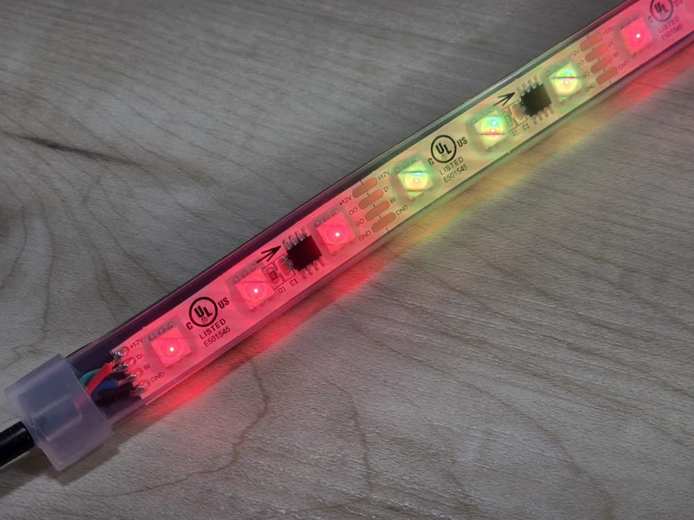
Figure 2: Two 8-pin driver chips are seen in this image of the Banner LED strip.
What are the mandatory accessories for the WLF12?
A control module is required to interface the LED strip with the traditional 24 VDC industrial system. This controller provides low voltage DC power to the LED drivers and sends the appropriate communication signals to the LED driver chips.
This article is focused on the LC25C-WLF12-RGB7Q to provide a direct to PLC interface. You may prefer to use the LC25C-WLF12-KQ for IO-Link or the LC25C-WLF12-SQ for a Modbus network.
How to Connect the WLF12 to the PLC Using the LC25C-WLF12-RGB7Q Controller
There are two ways to connect the LC25C-WLF12-RGB7Q Controller to the PLC.
Single-wire control
Figure 3 presents the programming interface and the wiring diagram for the WLF12 as configured for the author’s S7-1200 PLC interface. The controller features a M12 connector with standard coloring:
- Brown: 24 VDC
- Blue: Return for 24 VDC
- White for the PWM / PFM control signal
As a rule of thumb, the Banner single-wire interface provides four control options as shown in Figure 3.
Multi-wire control
The LC25C-WLF12-RGB7Q is equipped with a 4-pin M12 connector. The WLF12 can be programmed to use all wires for control:
- Brown, white, and black for power and signaling
- Blue: Return for 24 VDC
Given three control wires, we have 8 possible control options, one of which is no power to the device. A representative example is shown in Figure 4 (the no power state is not shown).
Which connection is the best?
All PLCs have limited I/O resources. For example, the featured Siemens PLC has 10 semiconductor outputs, 4 of which have high-speed (hardware-based) pulse generators. With respect to the Banner WLF12 we have two choices:
- Consume 3 of the 10 digital (semiconductor) outputs
- Consume 1 of the precious pulse generators
Tech Tip: The PLC I/O limitation may be overcome with expansion modules or the increasingly popular networked options such as IO-Link or the venerable MODBUS.

Figure 3: Programming interface and wiring diagram for the WLF12 to S7-1200 PLC interface.
Tech Tip: Most of you are already familiar with Pulse Width Modulation (PWM) where the frequency is fixed, and the pulse width is varied. Pulse Frequency Modulation (PFM) is related but opposite. With PFM, the duty cycle is fixed at 50%, and the frequency is changed.
As an experiment we can connect a loudspeaker to the PFM signal. It would sound like an old 8-bit video game as it shifted frequency.

Figure 4: WLF12 configured for machine process visualization using a three-wire control interface.
Interfacing the WLF12 with the Siemens S7-1200 PLC
For this demonstration, the single-wire PFM option was chosen:
- Preserving the PLC’s limited I/O was more important than consuming a pulse generator.
- Personally, I find the Siemens PFM control block easier to use. As shown in Figure 5 the frequency is associated with the block as opposed to PWM where an extra MOVE block is required to change the duty cycle.
Please refer to this Siemens document for configuration of the pulse generator.
Once configured, the command to the LED strip is passed to the FREQUENCY input of the CTRL_PTO block. The tag names in this project make me smile as we talk about the Banner LED display function as a frequency. It’s a bit disorienting when variables such as uiAlarmColor (Hungarian, ui for unsigned int) are passed to FREQUENCY.

Figure 5: Siemens PFM control block for a pulse generator.
Frequently Asked Questions:
Can the WLF12 be connected directly to the PLC?
No.
While the WLF12 does have a M12 connector, it is not compatible with the traditional 24 VDC industrial I/O.
A controller must be used to provide low voltage power as well as serial communication to control the individual LED driver as seen in Figure 2.
Tech Tip: Recommend heat shrink be used to cover the LED strip to controller M12 connection. This serves as a reminder that the LED strip and controller function as a single unit.
What additional resources are required to use the Banner WLF12 LED strip?
There are three control modules designed to best match your industrial control network including:
LC25C-WLF12-RGB7Q: Direct to PLC interface with either 3-wire control, PFM, or PWM.
LC25C-WLF12-KQ: IO-Link interface
LC25C-WLF12-SQ: Modbus interface
What is the current consumption for the Banner WLF12 LED strip?
Current consumption is a function of length. The longer LED strips can consume about 2A at full brightness. Consult the datasheet, and plan your power supply needs accordingly.
What can the Banner WLF12 LED strip be used for?
The best answer is to explore the configurations from within Banner’s Pro Express software. Here are a few options:
-
Display machine status using traditional red, yellow, and green states.
-
For a visually stunning display use a windowed enclosure and wrap the LED strip around the inside of the cabinet. This is like mood lighting for the PLC.
-
Alternatively, embed the LEDs into one of the T-slot pillars of the machine.
-
Leverage the additional colors to assist operators. For example, white to indicate changeover of a tool or part.
-
-
Display quantity including fluid levels, time, count or any other value that may be captured in your PLC using a type int tag.
-
Display physical location by lighting the appropriate LED segment. This could be a simple linear display to show the location of a part. We could also use two LED strips to show an X-Y location. DigiKey sells units from 300 to 4025 mm (approximately 1 to 13 ft) lengths to accommodate this linear positioning.
Parting Thoughts
Banner provides unique visual indicators ranging from the K50 touch button to the WLF12 LED strip. Surprisingly, these two devices have much in common especially when we consider the common software and programming hardware.
Please share your ideas for how this LED strip could be used in your application.
Best wishes,
APDahlen
 Continue Exploring Industrial Control Systems
If this discussion was helpful, you may also want to explore:
 DigiKey Navigation
- Full Catalog: Industrial Control & Automation
 Related Foundational Articles
- Building a State Machine in Siemens TIA Portal
- Beyond Specs: Soft Requirements for Selecting the Right PLC
- How to Configure the FirstScan Bit in Siemens TIA Portal
- Navigating Siemens S7-1200 PLC model numbers
About This Author
Aaron Dahlen, LCDR USCG (Ret.), is a Senior Applications Engineer at DigiKey in Thief River Falls. His background in electronics and industrial automation was shaped by a 27-year military career as both technician and engineer, followed by over a decade of teaching.
Dahlen holds an MSEE from Minnesota State University, Mankato. He has taught in an ABET-accredited electrical engineering program, served as coordinator of an electronic engineering technology program, and instructed military technicians in component-level repair.
Today, he has returned to his home in northern Minnesota, completing a decades-long journey that began with a search for capacitors. Read his story here.