Summary
Look at any picture of the Siemens ET 200SP distributed I/O, and you will immediately notice that there are two different colors for the base units (BU) into which plug-in modules are inserted. The Siemens literature associates the colors with a “potential group.”
In this engineering brief, we examine the physical hardware to better understand the Siemens potential groups. We then consider equipment design with isolated sections to improve reliability with UPS backup of critical sections such as the HMI and control logic.
Representative base units are shown in Figure 1, including:
-
White: New potential group (load group) base unit type 6ES7 193-6BP00-0DA0.
-
Gray: Standard base unit type 6ES7 193-6BP00-0BA0.
This article is part of DigiKey’s Siemens PLC and Automation Resource Hub. Visit the hub for more technical briefs on Siemens components, applications, and programming.
![]() Estimated reading time: 7 minutes
Estimated reading time: 7 minutes
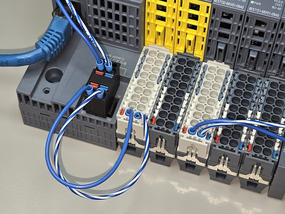
Figure 1: Close up view of the ET 200SP base units showing a daisy chain connection to the first base unit.
TL;DR
Siemens ET 200SP Load Groups (aka “Potential Groups”):
-
White base (BU): Starts a new 24 V load group. No bus pickup on the left. Must feed power directly.
-
Gray base (BU): Extends the existing load group. Passes bus power along.
-
Rule of thumb: Each group limited to ~10 A. Keep it under ~7 A to be safe.
-
Why groups? Short in one group won’t kill the others. Easier troubleshooting, lets you add UPS to critical stuff.
-
Don’t mix blindly: Okay in design, maybe in mods, never during repair—swapping BUs changes load groups and can bite you.
Bottom line: Use white bases to break up the bus when current or reliability demand it.
This TL;DR was written by an AI assistant that wants to BLUF (place the Bottom Line Up Front). The remainder of the article is human written.
Terminology note: Siemens ET 200SP literature uses the term “potential group” (Potentialgruppe in German). For clarity, think load group. Both terms will be used interchangeably in this document.
How is power distributed in the ET 200SP?
Figure 2 shows a close-up image of the power distribution connections for the ET 200SP. Observe:
-
The base modules plug into each other. A green dot has been placed next to the physical power distribution connections.
-
The ET 200SP interface module (proper) does not participate in the power distribution. In fact, there are no power connections included on the featured 6ES7155-6AU01-0CN0. Instead, we see a slight (empty) indentation near the red dot in Figure 2.

Figure 2: Close up image showing the power distribution connection (green dot).
The White BU do not Accept Power
A lack of power connection prevent the white BU from accepting power from the bus. Look closely at Figure 3, we see that the white BU has no copper contacts for the left side (power pickup). Consequently, the white (new load) base units provide isolation between power sections.

Figure 3: There are no power input connections in the white base unit.
Tech Tip: The first base unit immediately following the ET 200SP interface module should be a white (new load group) type. To be sure, we can power a gray unit via the power connections (Figure 1). However, there is something to be said about following the convention implicit in the Siemens design.
The white modules must be directly connected to the power source.
The gray modules power connection should be unconnected, as the gray modules receive power from the white new load group module to the left.
What is a potential group?
A potential group is a group of field devices that share a common supply. Stated another way, if a short develops on a field device, it trips the group but not the other groups.
-
General definition: The term potential group may be applied generally to a PLC where we often see grouped output sections that require their own power supply connections. For example, a PLC may have eight relay outputs. Two potential groups are formed if two power nodes are established where each provides power to 4 relay contacts. If we think in terms of a sourcing configuration, where four loads are supplied by four relays which are in turn are sourced by two independent circuit breakers.
-
Siemens ET 200SP definition: The term is specifically applied to the Siemens ET 200SP as a way of isolating contiguous sections of the of the ET 200SP. As seen in Figure 2, the isolation involves the 24 VDC supply. The communication handles across all devices via an independent bus connection (not shown).
As a counter definition, if we tie all the supply and return terminals together, everything is in one potential group. This occurs even though the white ET 200SP isolators are used.
Tech Tip: Consider adding a 24 VDC UPS to your control panel. The minimal set of equipment powered by the UPS is placed on an independent backup potential group. This could include the control logic (PLC or distributed I/O), HMI, and limited pilot devices. Here the term pilot includes front panel selector switches and panel lamps.
How much current can the Siemens ET 200SP bus handle?
As a case study, let’s take a closer look at the 6ES7132-6BH01-0BA0. This plug-in unit is advertised as a 16-output solid state output module with each output rated for up to 500 mA.
In theory, with all outputs activated, this module can source 8 A. In practice, we need to pay close attention to the system level details.
-
What is an ET 200SP process terminal? The process terminal is the physical connection to the plug-in module. Continuing with the previous example, the 6ES7132-6BH01-0BA0 has 16 process terminals.
-
What are the ET 200SP P1 and P2 terminals? The P1 and P2 terminal are shown are the wire connections as shown in Figure 1. We can slide this definition slightly with an implication that the bus connectors as shown in Figure 2 also carry a maximum of 10 A. Internally, these are connected to the P1 and P2 terminals.
Answer
A simple answer suggests that we can cavalierly use the 0.5 A per channel 16-channel plug-in unit to its full capacity. In practice, this is only true if modules are operated in isolation with each unit on an isolated white new load group base.
Realistic Answer
We accommodate the current limitation of base unit, load group, power supply, and the DC supply wires to the modules. While we were content to use our 16-channel module in isolation, what happens if we use two such units, one on a white base and the other on a grey base. Let’s further assume that power is provided directly to the white base unit.
In this case, we are limited to a combined total of 10 A. Activation of all 32 outputs with all outputs driving full load would overload the bus.
To be sure, we almost never drive all outputs to full capacity. However, we may add many modules to the load group inadvertently causing an over current condition.
Tech Tip: Perform a power assessment for each potential group. As a practical engineer’s rule of thumb, start a new load group when the current approaches about 75 % of bus carrying capacity (approximately 7 A).
Why not establish a single big load group?
This may be the best solution for a small system. We simply connect all devices to a single 24 VDC power supply. However, it is undesirable for larger machines given the previously addressed current limitations.
Larger systems may also benefit from a troubleshooting or redundancy perspective. Remember that a short circuit will take down the entire load group. Therefore, it may be beneficial to establish independent load groups each equipped with its own current monitoring and protection. As an example, a solid state electronics circuit breaker could be used to protect each load group.
As a case study consider a mid-sized machine:
-
Isolate the distributed I/O, networking components, and pilot devices as an independent load group. Consider adding a 24 VDC UPS to this group to provided limited control and monitoring capabilities in the event of a power loss. What do you want the machine to do when you are in the dark.
-
Logically segregate the machine into sections. As an example, consider a simple left- and right-hand load group segregation.
A machine with load group isolation will be considerably easier to troubleshoot. Also, we can add current monitoring for the left- and right-hand sections. Finally, knowing that a section is down, we could add mitigation routines. These could be as simple as a controlled shutdown or as complex as left- to right-hand redundancy.
Why not exclusively use the white new load group base?
This could certainly be done. However, there are a few reasons to avoid this practice:
-
The white new load group base units are slightly more expensive.
-
Additional wiring is required for each white new load group base.
-
Additional design-dependent circuit protectors may be required for each load group.
Can the standard gray and white new load group modules be swapped?
For clarity, let’s answer this question based on where we are in the lifecycle of the machine:
-
Greenfield: The designer is free to choose modules based on the system constraints such as cost, reliability, and ease of troubleshooting.
-
Modification: The designer is free to swap modules provided the load analysis is complete and there are no undesirable changes in the machine’s operation. For example, a swap to a new load group may be desirable for a problematic load. Don’t forget to update the prints.
-
Troubleshooting and repair: This is a hard no! Swapping base modules may inadvertently change the load group assignments with potentially hazardous results.
Parting Thoughts
The importance of load segregation increases with the complexity of the system. A small system including an ET 200SP with a few modules may all share a single load group. Larger systems may require load segregation due to current limitations or as mitigation for fault detection and correction.
Your feedback is appreciated, What is missing from this document?
Best wishes,
APDahlen
Related Articles by this Author
If you enjoyed this article, you may also find these related articles helpful:
-
Use the Siemens first scan bit as an initializer in your program: How to Configure the FirstScan Bit in Siemens TIA Portal
-
The Banner LED strip provides flare and utility to your project from simple RGB alarm display to tank-sized level indicators: Integrating the Banner WLF12 Flexible LED Light Strip with a PLC
-
Compare state machines across multiple Siemens languages. This is the first article in a series: Building a State Machine in Siemens TIA Portal
About This Author
Aaron Dahlen, LCDR USCG (Ret.), serves as an application engineer at DigiKey. He has a unique electronics and automation foundation built over a 27-year military career as a technician and engineer which was further enhanced by 12 years of teaching (interwoven). With an MSEE degree from Minnesota State University, Mankato, Dahlen has taught in an ABET-accredited EE program, served as the program coordinator for an EET program, and taught component-level repair to military electronics technicians.
Dahlen has returned to his Northern Minnesota home, completing a decades-long journey that began as a search for capacitors. Read his story here.