本文示範如何 同時連接與讀取多顆 Analog Devices DS18B20 溫度感測器。DS18B20 採用 1‑Wire 通訊協定,具 CRC 資料完整性檢查。這種 1-Wire 介面利用數據線本身的能量,省去外接 VDD 供電線。每顆裝置擁有 唯一的 64-Bit 雷射燒錄 ROM Code,

因此 多顆感測器可共享同一條 1‑Wire 匯流排,非常適合大範圍的分散式溫度量測,例如:環境監控、樓宇控制、機台/製程監控與工業設備。
DS18B20 特色重點(Features)
- 1‑Wire® 單埠通訊:只需一個 I/O 腳即可通訊
- 整合感測器與 EEPROM:降低系統用料
- 量測範圍:−55°C ~ +125°C(−67°F ~ +257°F)
- 精度:±0.5°C(−10°C ~ +85°C)
- 解析度可程式化:9/10/11/12 Bits(預設 12 Bits)
- 寄生供電模式:只需 DQ 與 GND 兩腳即可運作,無需外接 VDD
- 多點佈建:支援 Multidrop 並聯
- 唯一序號:每顆具 64‑bit ROM(支援搜尋/配對)
- 非揮發性(NV)警報設定,以及警報搜尋指令,可辨識溫度超出預設限值的設備
- 封裝:8‑pin SO(150 mil)、8‑pin µSOP、3‑pin TO‑92
示範: 使用 TO‑92 封裝 的三顆 DS18B20

DS18B20 溫度感測器的框圖如下:

DS18B20 工作原理與資料格式
DS18B20 的核心功能是其直接數位式溫度感測器。
- 解析度:9/10/11/12 bits(透過配置暫存器), 分別對應 0.5/0.25/0.125/0.0625°C;上電預設 12 bits
- 輸出單位:溫度以 攝氏(°C) 標定;若要 華氏(°F) 請自行轉換 (對於華氏溫度應用,必須使用查找表或轉換例程。)
- 溫度資料格式:溫度資料以 16 bit 符號擴展的二進位補碼數形式儲存在溫度暫存器中,如下表所示。

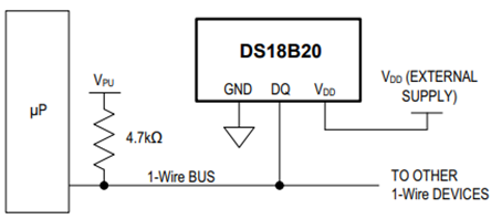
如果需要,DS18B20 也可以採用傳統的供電方式,即將外部電源連接到 VDD 接腳,如下圖所示。
DS18B20 的內部記憶體佈局如下圖所示,

此記憶體由一個 SRAM 暫存區和一個非揮發性 EEPROM 組成,其中 EEPROM 儲存高低警報觸發暫存器 (TH) 和配置暫存器。請注意,如果未使用 DS18B20 警報功能,則 TH 和 TL 暫存器可用作通用記憶體。
匯流排主控器使用 ROM 指令 (0x55) 尋址要通訊的 DS18B20 後,即可發出 DS18B20 功能指令。這些命令允許主控器對 DS18B20 的暫存區記憶體進行讀寫操作、啟動溫度轉換以及確定電源模式。 DS18B20 功能指令如下表所示。

示範配置
以下示範中使用了一些配置,包括
- Raspberry Pico 2 W 評估板
- 透過 Pin 36 提供 3.3V 電壓,Pin 38 提供參考電壓
- 三顆 DS18B20 溫度感測器
- 在 GPIO 15(Pin 20)上連接 3.3V 上拉電阻,作為 1-Wire 資料匯流排

為了示範 DS18B20 溫度感測器的同作能力,我們在 1-Wire 匯流排上放置了三顆 DS18B20 溫度感測器。使用 Raspberry Pi Pico 2W 平台,並利用其內部 PIO 狀態機 onewire_library.pio 創建了自訂的 1-Wire 通訊協定接口,並透過 C SDK 中的 C 應用程式進行存取。本示範中使用:
onewire_library.pio PIO 狀態機定義檔
;
; Copyright (c) 2023 mjcross
;
; SPDX-License-Identifier: BSD-3-Clause
;

; Implements a Maxim 1-Wire bus with a GPIO pin.
;
; Place data words to be transmitted in the TX FIFO and read the results from the
; RX FIFO. To reset the bus execute a jump to 'reset_bus' using the opcode from
; the provided function.
;
; At 1us per cycle as initialised below the timings are those recommended by:
; https://www.analog.com/en/technical-articles/1wire-communication-through-software.html
;
; Notes:
;   (1) The code will stall with the bus in a safe state if the FIFOs are empty/full.
;   (2) The bus must be pulled up with an external pull-up resistor of about 4k.
;       The internal GPIO resistors are too high (~50k) to work reliably for this.
;   (3) Do not connect the GPIO pin directly to a bus powered at more than 3.3V.

.program onewire
.side_set 1 pindirs

PUBLIC reset_bus:
        set x, 28       side 1  [15]    ; pull bus low                          16
loop_a: jmp x-- loop_a  side 1  [15]    ;                                  29 x 16
        set x, 8        side 0  [6]     ; release bus                            7
loop_b: jmp x-- loop_b  side 0  [6]     ;                                    9 x 7

        mov isr, pins   side 0          ; read all pins to ISR (avoids autopush) 1
        push            side 0          ; push result manually                   1
        set x, 24       side 0  [7]     ;                                        8
loop_c: jmp x-- loop_c  side 0  [15]    ;                                  25 x 16

.wrap_target
PUBLIC fetch_bit:
        out x, 1        side 0          ; shift next bit from OSR (autopull)     1
        jmp !x  send_0  side 1  [5]     ; pull bus low, branch if sending '0'    6

send_1: ; send a '1' bit
        set x, 2        side 0  [8]     ; release bus, wait for slave response   9
        in pins, 1      side 0  [4]     ; read bus, shift bit to ISR (autopush)  5
loop_e: jmp x-- loop_e  side 0  [15]    ;                                   3 x 16
        jmp fetch_bit   side 0          ;                                        1

send_0: ; send a '0' bit
        set x, 2        side 1  [5]     ; continue pulling bus low               6
loop_d: jmp x-- loop_d  side 1  [15]    ;                                   3 x 16
        in null, 1      side 0  [8]     ; release bus, shift 0 to ISR (autopush) 9
.wrap
;; (17 instructions)


% c-sdk {
static inline void onewire_sm_init (PIO pio, uint sm, uint offset, uint pin_num, uint bits_per_word) {

    // create a new state machine configuration
    pio_sm_config c = onewire_program_get_default_config (offset);

    // Input Shift Register configuration settings
    sm_config_set_in_shift (
        &c,
        true,           // shift direction: right
        true,           // autopush: enabled
        bits_per_word   // autopush threshold
    );

    // Output Shift Register configuration settings
    sm_config_set_out_shift (
        &c,
        true,           // shift direction: right
        true,           // autopull: enabled
        bits_per_word   // autopull threshold
    );

    // configure the input and sideset pin groups to start at `pin_num`
    sm_config_set_in_pins (&c, pin_num);
    sm_config_set_sideset_pins (&c, pin_num);

    // configure the clock divider for 1 usec per instruction
    float div = clock_get_hz (clk_sys) * 1e-6;
    sm_config_set_clkdiv (&c, div);

    // apply the configuration and initialise the program counter
    pio_sm_init (pio, sm, offset + onewire_offset_fetch_bit, &c);

    // enable the state machine
    pio_sm_set_enabled (pio, sm, true);
}

static inline uint onewire_reset_instr (uint offset) {
    // encode a "jmp reset_bus side 0" instruction for the state machine
    return pio_encode_jmp (offset + onewire_offset_reset_bus) | pio_encode_sideset (1, 0);
}
%}
main.c 範例
/**
 * Copyright (c) 2023 mjcross
 *
 * SPDX-License-Identifier: BSD-3-Clause
**/

#include <stdio.h>
#include "pico/stdlib.h"
#include "pico/binary_info.h"

#include "onewire_library.h"    // onewire library functions
#include "ow_rom.h"             // onewire ROM command codes
#include "ds18b20.h"            // ds18b20 function codes

// Demonstrates the PIO onewire driver by taking readings from a set of
// ds18b20 1-wire temperature sensors.

int main() {
    stdio_init_all();

    PIO pio = pio0;
    uint gpio = 15;

    OW ow;
    uint offset;
    // add the program to the PIO shared address space
    if (pio_can_add_program (pio, &onewire_program)) {
        offset = pio_add_program (pio, &onewire_program);

        // claim a state machine and initialise a driver instance
        if (ow_init (&ow, pio, offset, gpio)) {

            // find and display 64-bit device addresses
            int maxdevs = 10;
            uint64_t romcode[maxdevs];
            int num_devs = ow_romsearch (&ow, romcode, maxdevs, OW_SEARCH_ROM);

            printf("Found %d devices\n", num_devs);
            for (int i = 0; i < num_devs; i += 1) {
                printf("\t%d: 0x%llx\n", i, romcode[i]);
            }
            putchar ('\n');

            while (num_devs > 0) {
                // start temperature conversion in parallel on all devices
                // (see ds18b20 datasheet)
                ow_reset (&ow);
                ow_send (&ow, OW_SKIP_ROM);
                ow_send (&ow, DS18B20_CONVERT_T);

                // wait for the conversions to finish
                while (ow_read(&ow) == 0);

                // read the result from each device
                for (int i = 0; i < num_devs; i += 1) {
                    ow_reset (&ow);
                    ow_send (&ow, OW_MATCH_ROM);
                    for (int b = 0; b < 64; b += 8) {
                        ow_send (&ow, romcode[i] >> b);
                    }
                    ow_send (&ow, DS18B20_READ_SCRATCHPAD);
                    int16_t temp = 0;
                    temp = ow_read (&ow) | (ow_read (&ow) << 8);
                    printf ("\t%d: %f C", i, temp / 16.0);

                    //Convert from C to F (Simple conversion for test purposes only)
                    float K1 = 1.8;
                    float K2 = 32.0;
                    float temp_F = temp*K1/16.0 + K2;
                    printf ("\t%d: %f F", i, temp_F);

                }
                putchar ('\n');
            }

        } else {
            puts ("could not initialise the driver");
        }
    } else {
        puts ("could not add the program");
    }

    while(true);
}
編譯與燒錄
程式編譯後依下列步驟燒錄到 Raspberry Pico 2 W 中:
DigiKey_Coffee_Cup # make -j8
DigiKey_Coffee_Cup # picotool load pio_onewire.uf2
邏輯分析與協定觀察
以 SparkFun 邏輯分析儀 觀測 1‑Wire 協議。如下所示。重新啟動 Raspberry Pico 2 W 後,定期輪詢的 3 個 Analog Devices DS18B20 溫度感測器的讀數如下所示。

透過 minicom 終端和上方所示的 Sparkfun 邏輯分析儀捕獲的數據,確認了 3 個 Analog Devices DS18B20 溫度感測器的 64-bit 雷射刻錄 ROM 代碼。接下來這張來自先前連結中設定的 Sparkfun 邏輯分析儀的截圖,放大顯示了 1-Wire 網路層(類似於內建的 Analog Devices DS28EA00 溫度感測器協定解碼器)、重設/存在偵測過程以及 ROM 指令 (0x55)(只有與 64-bit ROM 程式碼序列是完全匹配裝置從裝置上從裝置上發出的脈衝。此外,下方還顯示了 3 個共用 1-Wire 匯流排的 Analog Devices DS18B20 溫度感測器中被查詢感測器的回應。

Sparkfun 邏輯分析儀內建 1-Wire(link layer)和 1-Wire(network layer)接口,本示範中使用的是類似 Analog Devices DS28EA00 溫度感測器的 1-Wire 協定解碼器,如上圖所示。 Sparkfun 邏輯分析儀可依需求簡化設計、測試和故障排除流程。
本示範展示如何使用 Raspberry Pico 2W 和 C SDK,透過 1-Wire 線路連接 3 個 Analog Devices DS18B20 溫度感測器。 DS18B20 溫度感測器是分散式溫度感測設計的理想選擇,特別適用於對系統控制線數量有限制的應用。其寄生功率模式僅需 2 個 Pin (DQ 和 GND)即可運作,簡化了具有多點連接的分佈式溫度感測應用。這款功能強大的 Analog Devices DS18B20 溫度感測器可從 DigiKey 購買。
與 DS28EA00 的比較與延伸
若需要更強韌的 1‑Wire 介面與更多 I/O 彈性,可考慮 DS28EA00(具介面遲滯與假電子信號 Glitch 濾波、兩個通用可程式 PIO Pin、Chain State Transition 可偵測網路中裝置的物理順序),用於更複雜的多節點場景。
