This engineering brief identifies recurring pain points when dealing with A-coded (5-pin) M12 devices and cabling.
Myth: All visible M12 connector pins are internally wired.
Reality: This is a non-visible myth describing an incorrectly wired system. You will burn time and money troubleshooting sensors and hubs when the real problem lies with the cable.
A-coded M12 connectors are nominally described as 5-pin devices. However, not all field devices require all 5 conductors. To save cost, the number of conductors in the cable is reduced. For example, a simple on-off switch requires two wires (brown and black) while a complex sensor may use all five. While the cables are different, the visible male and female connectors are often the same.
The visible pin count may be misleading, as the number of pins may not match the number of conductors in the cable.
This is a serious problem during equipment maintenance or modification. An incorrectly selected cable complicates troubleshooting, increasing cost, and extends plant downtime.
My recommendation is to assume the cable is wrong until the construction is verified against the datasheet or a continuity test is performed.

Figure 1: A-code 5-pin connector with only the conductors in the cable.
Myth: All ports on a machine-mounted IO-Link master or on a digital hub are the same.
Reality: This is a latent myth that becomes visible when equipment is modified (brown vs green field). You will underestimate the number of I/O or overestimate the power that can be delivered to the field device.
Visual inspection does not indicate function. Digital hubs may look standard but that assumption could cost you down the line.
The 5-pin A coded M12 female connector is industry standard for machine-mounted IO-Link masters and general purpose digital hubs. They all look the same, yet port functionality varies between devices and even for the ports on a single device.
The SICK SIG300 demonstrates this pain point (Figure 2). While it has eight A-coded connectors there are three different types. All are IO-Link capable but differ in their digital I/O capability:
-
Class A1: Ports S1 through S4 expose 4-pins including 24 VDC, return, and two bidirectional signaling ports.
-
Class A2: Ports S5 and S6 expose all 5 pins including 24 VDC, return, and three bidirectional signaling ports. A configuration window is included as Figure 3 showing pins 2 and 4 as digital outputs and pin 5 as a digital input.
-
Class B: Ports S7 and S8 are high power ports capable of providing up to 2A. All 5 pins are exposed including 2 pins for 24 VDC, 2 pins for return, and a signal wire. Recall that a class B port doubles the power conductors for increased current capability.
This presents a system configuration problem with long term complications for system expansion. It’s a resource constraint problem as there is a limited amount of I/O. If we mistakenly assume all 5 pins are exposed, we end up 8 I/O ports less than expected.
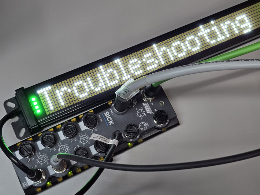
Figure 2: This SICK SIG300 includes eight A-coded M12 connectors.

Figure 3: Port configuration window for the SICK SIG300.
Myth: The ports for machine-mounted hubs are interchangeable.
Reality: This is a potentially dangerous latent fault for digital I/O, yet visible for IO-Link devices. You will inadvertently swap cables and spend hours troubleshooting a self-induced failure. Even worse, the machine will continue to operate with a hidden hazard. For example, consider what happens if the end stops are cross-wired.
The novice may assume the M12 ports operate interchangeably like the RJ-45 connections on a home Ethernet. There is nothing that prevents a field device from being plugged into the wrong M12 port. This is a serious pain point in the 3 AM fog of troubleshooting. You may inadvertently swap cables on the hub. Worse yet, the field devices may be swapped downstream at the end of an extension cable
Industrial M12 connections are strictly mapped as if they were directly connected to a PLC’s screw terminal I/O.
M12 is not Ethernet!
A strict application of wire labeling standards is the first line of defense. The hub’s status LEDs may be used to monitor the input and output signals. As a last resort, the PLC diagnostic will report IO-Link errors.
Myth: The PLC is in control of the machine-mounted hub.
Reality: This is a latent myth involving loss of software. Note that control may be split between the PLC and a smart IO-Link master. Without proper version control and documentation, the line will be down for hours or even days. The worst-case scenario is a hard failure of the IO-Link master with no ability to read the code. You can’t restart the line without reconstructing the code.
The logic editor for the SIG300 as shown in Figure 4 presents a trivial example. Here the digital input for port S1 input pin 2 is routed to port S1 output pin 4. This code lives in the SIG300. The PLC may or may not be aware of the relationship. This is increasingly true as the intelligence of the IO-Link master increases. In fact, devices like the SIG300 operate with PLC functionality of logic and timers.
The life cycle of industrial equipment is measured in decades. It is imperative that maintenance crew maintain the gold disk that contains the latest code. Also, clearly mark the engineering tools required to program the equipment. For example, don’t let the IT department commandeer the old laptop.

Figure 4: SICK Logic editor windows showing port 1 pin 2 directly driving port 1 pin 4.
Related Articles by this Author
If you enjoyed this article, you may also find these related articles helpful:
- How to Clear PLC to SICK SIG300 Errors
- Guide to Troubleshooting Industrial Control and Automation Equipment
- What software files are required for IO-Link?
About This Author
Aaron Dahlen, LCDR USCG (Ret.), serves as an application engineer at DigiKey. He has a unique electronics and automation foundation built over a 27-year military career as a technician and engineer which was further enhanced by 12 years of teaching (interwoven). With an MSEE degree from Minnesota State University, Mankato, Dahlen has taught in an ABET-accredited EE program, served as the program coordinator for an EET program, and taught component-level repair to military electronics technicians.
Dahlen has returned to his Northern Minnesota home, completing a decades-long journey that began as a search for capacitors. Read his story here.