Switching power supplies create undesired EMI noise, usually at the harmonic of their switching frequency or coherent to the switching frequency. Due to the wide bandwidth of power supply noise, an oscilloscope is often the preferred tool for measuring this noise. Using an oscilloscope to measure this noise requires special attention.
Measuring a switching power supply’s noise via oscilloscope probe is performed as close as physically possible to the power supply output terminals. This reduces the radiated noise received and improves the quality of your measurement. The main measurement error usually comes from the unshielded portion of the probe. To reduce this error, unshielded leads must be kept as short as you can possibly manage.
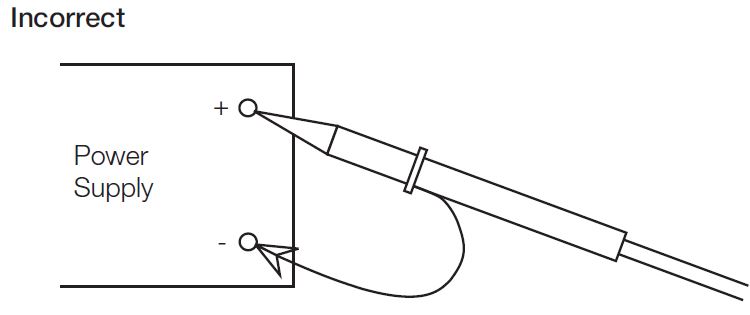
The below figure shows an incorrect measurement set-up, because the ground wire of your probe will act as an antenna and pick up the radiated noise from your power supply. The accuracy of your oscilloscope’s measurement is dependent on the probe’s physical position and the ground lead length.
Before you take your measurement, remove the clip-on ground wire and the probe body fishhook adapter from your probe. Then, attach a special tip and ground lead assembly, as shown in this figure.

Afterward, the ground ring of the probe is connected directly to the output ground of the power supply and the tip is in contact with the output voltage pin of the power supply. This eliminates as much radiated interference as possible and will give you the cleanest measurement of your switching power supply’s noise.