Created by Taylor Roorda
Introduction
Operational amplifiers, or op amps, are one of the fundamental building blocks of many electronic designs. They are incredibly versatile and can find a place in nearly any application. Uses can range from simply making a small signal larger to advanced analog signal processing. The following article seeks to summarize the basic parameters used to describe op amps, focusing primarily on those used on Digi-Key’s website at the time of this writing.

Image source: Wikimedia Commons / CC-BY-SA-3.0 / GFDL
The Ideal Model
Before looking at the specifications of a real op amp, it is important to understand the ideal op amp model to establish a reference. The ideal model exists to make the math involved in design easier, but cannot exist in practice. Some of the characteristics of an ideal op amp are:
- Infinite gain
- Infinite input impedance
- Infinite bandwidth - the op amp’s gain is not affected by frequency.
- Infinite slew rate - the op amp’s output can change as fast as it needs to.
- Zero input bias current - no current flows into the input terminals.
- Zero input offset voltage - the op amp’s output is zero when its inputs are equal.
Keep these parameters in mind when looking through the realistic parameters below.
Specifications
Like many ICs, op amps have a wide variety of specifications to keep in mind. The following list breaks down the parameters used by the Digi-Key filters for the op amp family.
-
Amplifier Type
- Most op amps fall under the General Purpose category, however there are many other categories that some op amps may fall into.
- Audio - These op amps are optimized for low noise and distortion for audio. The amps in this category do not have an output power stage.
- Buffer - The op amp is pre-configured to be used as an analog buffer, normally with unity gain. These typically only have one input and cannot be used as a normal op amp.
- CMOS - CMOS process technology is used in the op amp rather than a traditional bipolar process. CMOS op amps typically have higher input impedance and lower power consumption than bipolar devices.
- Current Feedback - An op amp with an output that is proportional to current rather than voltage. These op amps typically have a faster slew rate and frequency-independent gain.
- Current Sense - An op amp used to measure a small voltage drop across a resistor where the output voltage is proportional to the current through the resistor.
- Differential - All op amps are technically differential amplifiers, but are often used to amplify a single signal. A differential is designed to amplify the difference between two signals.
- Instrumentation - These amplifiers are most often composed of 3 separate amps. Typically inputs pass through buffer amplifiers and then are fed into a differential amplifier. These amps are designed for high precision, high input impedance, and high open-loop gain.
- Isolation - Op amps with a built in optoisolator to physically isolate the input from the output.
- JFET - Op amps made with JFET processes. These have higher input impedances and lower input bias currents than bipolar devices.
- Limiting - Amplifiers that can internally clamp the output voltage.
- Logarithmic - Amplifiers with an output that is proportional to the log of the input relative to a reference.
- Power - An op amp with an output power stage allowing it to source more current than a typical op amp.
- Programmable Gain - Op amps with variable gain that can be programmed digitally. This can be done with selection pins or through a serial interface like SPI.
- Sample and Hold - Typically used with ADCs, these amplifiers will hold an output value long enough for a conversion to complete.
- Transconductance - An amplifier that takes a voltage input and produces a current output.
- Transimpedance - An amplifier that takes a current input and produces a voltage output.
- Variable Gain - Similar to a programmable gain amp, but the gain may be controlled digitally or with an analog voltage.
- Voltage Feedback - Unless specified as a current feedback amplifier, all op amps use voltage feedback. This should be included in any general op amp search.
- Zero-Drift - Op amps that are characterized by low offset voltages and low offset drift with temperature.
-
Number of circuits
- Simply the number of individual op amps included in a single package. Typically either 1, 2, or 4.
-
Output type
An op amp normally has a single output that can swing between the range specified in the datasheet by VOL and VOH. This range is often significantly less than the range of VSS to VDD. For example, an op amp supplied with +/- 12V may only have an output swing of +/- 10V.
-
- (N/A) - Op amps with no special output type are specified with the dashed value in the Digi-Key filters. This covers the majority of op amps and should be included in most searches.
-
Differential - The op amp has both a positive and a negative output.
-
Rail-to-Rail - The op amp’s output voltage swing can go closer to the power rails than a traditional op amp. Typically in the millivolt range.
-
Open Drain - The op amp’s output pin is connected to the drain of a transistor. Therefore the op amp can only sink current.
-
Push-Pull - The output stage of the op amp uses a pair of transistors in a push-pull configuration where one transistor sources current and the other transistor sinks current.
-
Slew rate
- Slew rate measures how quickly the output of the op amp can change. The value is defined as the voltage change per unit time, typically given in V/μS.
- Inadequate slew rates cause distortion in the output waveform such as the one shown below. To avoid this distortion, the operating frequency must satisfy the following inequality:


Image source: Yves-Laurent Allaert / Wikimedia Commons / CC-BY-SA-3.0 / GFDL
-
The red square wave is the expected output, the green wave is the actual distorted output.
-
Gain bandwidth product
- The gain bandwidth product (GBP) describes the frequency response of an op amp. As the operating frequency increases beyond the cut-off frequency, the open-loop gain of the op amp decreases linearly with a constant slope. The frequency where the gain reaches unity is the GBP.

Image source: Wikimedia Commons
-
As shown in the figure above, decreasing the overall gain using feedback increases the overall bandwidth of the amplifier.
-
Example: An op amp with a 1 MHz GBP has a gain of 1 at 1 MHz or a gain of 100 at 10 kHz.
-
-3dB bandwidth
- The -3dB point is another way to specify the bandwidth of an op-amp. It corresponds to the point in the op amp’s frequency response where the gain begins to roll off.
-
Input bias current
- Due to the finite input impedance of a real op amp, a small amount of current is drawn by the inputs called the input bias current.
-
Input offset voltage
- The input offset voltage is the voltage across the input terminals required for the output to be zero. A lower value corresponds to a more precise op amp.
- Example: For an ideal op amp with V+ = 5V and V- = 5V, the output should be Vout = Av(V+ - V-) = 0V, where Av is the gain of the amplifier. However if the op amp has an offset voltage of 10mV, the conditions for an output of zero are V+ = 5.01V and V- = 5V.
-
Supply current
- Supply current is the current drawn by the op amp when no load is connected. Also known as quiescent current.
-
Output current
- The maximum current that can flow through the op amp’s output.
-
Supply voltage (single/dual)
- The range of voltages required for the op amp to function.
- Single supply op amps require only ground and a positive voltage rail.
- Dual supply op amps require a positive and negative voltage, ex +/- 15V.
- Many modern op amps can be operated with either single or dual supplies.
This of course does not exhaust the list of op amp specifications. There are others such as Total Harmonic Distortion, Common Mode Rejection Ratio, and more which may be important for certain applications. Unfortunately Digi-Key may not have these available to filter on the website. However, manufacturers will often have their own parametric search capability that includes these specifications.
For further reading, TI has an excellent white paper with a thorough breakdown of op amp specifications.
Common Circuits
Op amps are typically used in a closed loop configuration with negative feedback in order to maintain stability. In this case, the op amp’s output varies to try to force the input terminals to be equal. The examples below all use negative feedback.

Image source: Wikimedia Commons

Image source: Wikimedia Commons
-
Difference Amplifier
- Amplifies the difference between two signals.

- Constraining Rf / R1 = Rg / R2, the equation simplifies to:

- Amplifies the difference between two signals.
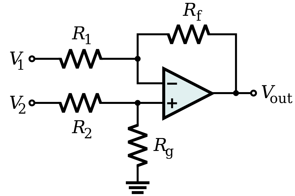
Image source: Wikimedia Commons

Image source: Wikimedia Commons
Image source: Wikimedia Commons

Image source: Wikimedia Commons

Image source: Wikimedia Commons

Image source: Wikimedia Commons
In the case of positive feedback the op amp’s output will swing to its supply rails, or as close as it can get. This is useful when a binary type output is desired. However, in these cases a dedicated comparator is usually preferred over an op amp.
Of course there are many more op amp circuits. The list above only covers a few of the most common topologies. For more examples, TI has another great application note on op amp circuits.
Conclusion
Op amps are a common component in analog systems and have a wide variety of uses. Applications can vary from simply amplifying a signal to creating voltage references or implementing filters. This article covered the basics of op amp specifications as well as some of the most common op amp circuits.
Video on Topic
Here’s a video take on the topic if you would like to check it out.
