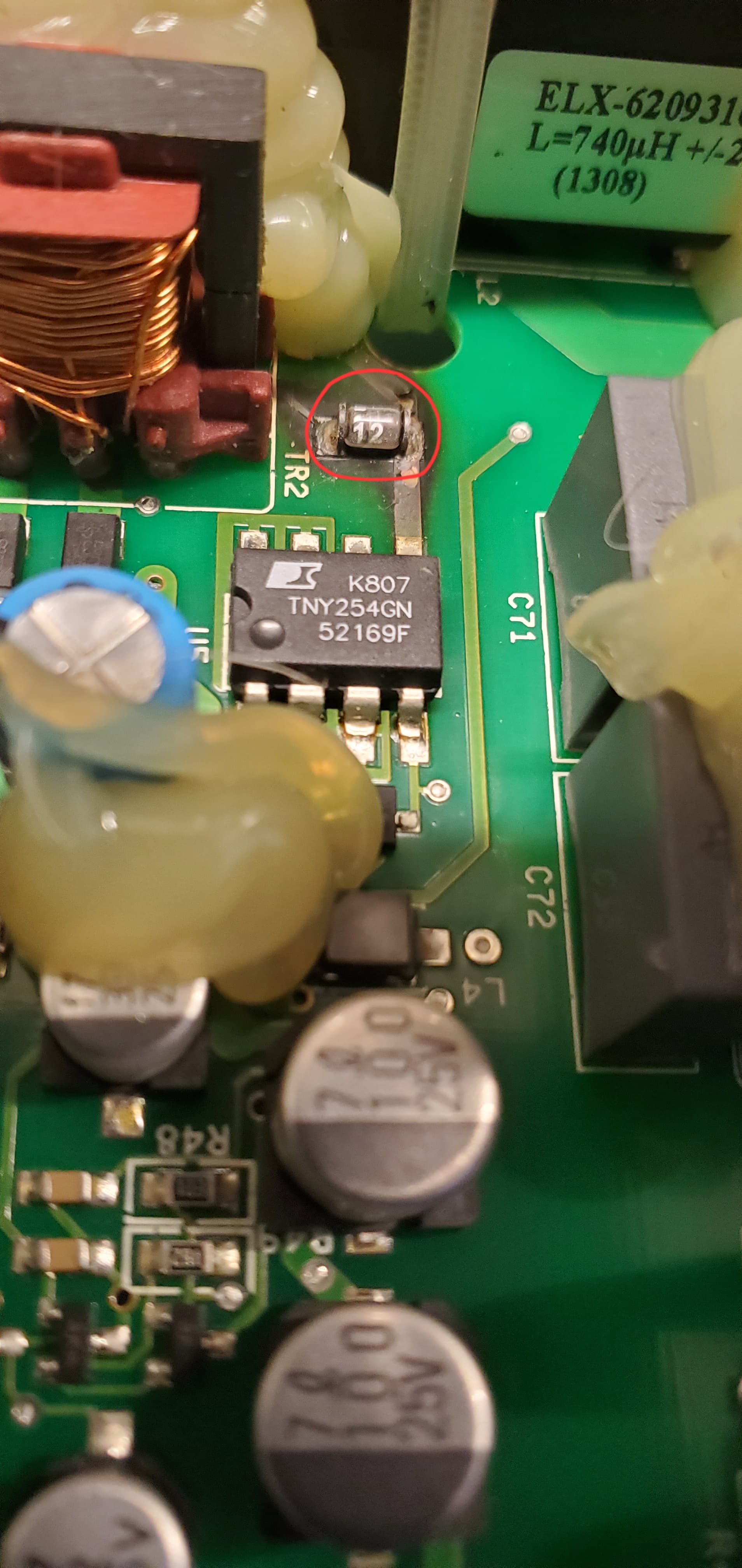
Hi. I need help identifying this smd. Only markings on it is the number ‘12’. Its in a glass casing. On 1 picture, the component is marked D6 on the board and on 1 picture the component doesnt have a marking. I suspect its some kind of diode but more info and cross reference would be helpful. Thanks.

Most parts in the leadless round package like that are indeed diodes of some form.
Identification from markings alone on such parts is a sketchy business; it’s much better to draw supporting info from the application context. In this case, it’s connected to pin 5 of a TNY254. If you look at the datasheet for that part, I suspect that what you’d see in figure 10 will look an awful lot like what appears on your board.
Hi and thank you for your reply/suggestion. So if I’m reading figure 10 correctly,I’m thinking your referring to diode 1N4937 (fast switching plastic ractifier). Correct me if I’m wrong.
That’s correct; if you see it connecting to a resistor, cap, etc. in the pattern of R1 & C2 of that diagram, you can be pretty confident that it’s being used in a similar capacity, and pick a replacement to try with similar characteristics; 600-800V voltage rating, fast recovery, ~1A average forward current.
Hi Rick. Heres a different schematic of the same principle (2 different motor control boards doing the same thing but abit of a different layout or blueprint). Those 2 black resistors are in place of that single glass diode. The red dots indicate the start/stop location of the trace wire on the back side of the board. Can you help me make sense of this.

Hello @joelmartin1234,
Those two parts are not resistors. The D designation on the prefix for D40 and D41 refers to Diode.
D40 marking UJ Should be Vishay General Semi Part number US1J. Datasheet - us1.pdf (vishay.com)

I couldn’t see the manufacturer logo on D41. But I believe that marking “160A” might be SZP6SMB160AT3G. Here is the spec sheet littelfuse_tvs_diode_szp6smb_datasheet.pdf.pdf
As for the Diode with the marking “12” in the MELF style package, I would say the same that the replacement should be 600v+ and 1Amp+. Please look at the diode options here and make sure to review the spec sheet before ordering to confirm the diodes dimensions will fit onto the PCB pads.
Thank you!
-Jeff
Hi Jeff. Thank you for your reply. Sorry,I did mean to note that D40 and D41 were diodes,not resistors. Saying that, the D40 and D41 placed in series cathode to cathode is doing the same job as the MELF style diode with the ‘12’ marking on it??
Assuming things have been traced out correctly, D41 would stand in for R1+C2 of figure 10, while D40 above and your original glass diode correlate to D1 in the figure.

That whole segment of things is a clamp network to prevent over-voltage conditions on the drain pin of the TNY254 as a result of the transformer’s leakage inductance. Since there’s no such thing as a perfect transformer, on every switching cycle there’s a bit of energy stored on the primary winding that can’t exit through the secondary, and it’ll tend to break things if not dissipated gently. If you’re jumping off the diving board at the swimming pool, it’s usually better if the pool has water in it. Same sorta idea here…