We use cookies to provide our visitors with an optimal site experience. View our privacy notice and cookie notice to learn more about how we use cookies and how to manage your settings. By proceeding on our website you consent to the use of cookies.
I have a dome light off a 17 honda civic, I would like to change some of the leds to be red. I was told I could use SMD2835 leds however, when I tried looking it up on the digikey site I didnt find one that looked like it.
I’m not sure how to find a suitable replacement red led for this dome light. Can someone please help me?
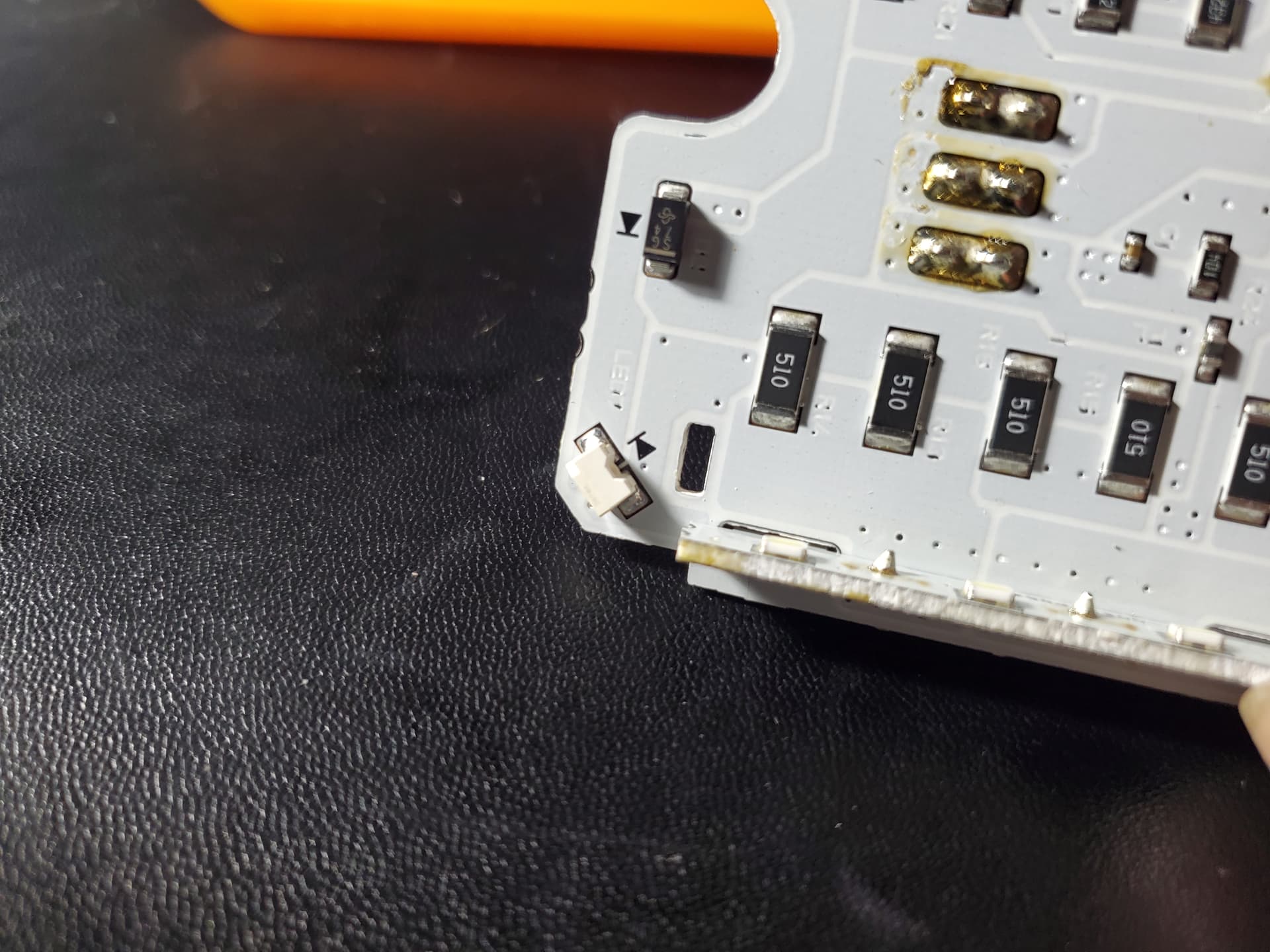
I have attached pictures to this thread of the leds on the board I want to change.
Thank you for contacting the Technical Forum. Do you have the physical size of the leds? I did not find an option that is the 2835 that looks like that either. If you could measure the leds to make sure of the size, that would be useful. We might be able to find other options. Though there is a chance if you change them out, it might not work. There most likely is not a current and voltage requirement you need . They might not match up to leds that are on this board. Let me know if you can provide any additional information.
That’s an unusual package type. Those are side-firing LEDs, right? The nearest thing we have to those are the “boomerang” type LEDs, but they are quite tall (4mm) and their contacts are spaced 2.54mm apart center to center (3.54mm outside to outside of contacts). Another thing to worry about with these is that they are only rated for 20mA. If your circuit board drives more than that through the LEDs, you’ll burn them out.
We do carry “2835” LEDs, but they look nothing like yours. They are low-profile (less than 1.0mm height) vertical firing LEDs. Since they are vertical, rather than horizontal firing, they may not work for you, but they do fit your footprint, and with their low profile, wide light viewing angle (120°), and high light output, they might actually work for you.
“2835” LED
If you want to give one a try, I’d recommend this one, as it is brighter than most, and can handle more current without burning out:
Thank you for your help. I measured the led on the board and its about 3mm in height, but it does look like I have enough room to fit a 4mm or slightly taller led. The space between the two contact points on the board is around 0.39mm and each pad is 3mm in length and about 2mn in width.
How can I verify the type of voltage rating I need? Is that something I can measure with a voltmeter?
If you can power up the board, you should be able to measure the voltage across the LED. If you can’t do that, it will be very difficult to know. However, a typical white LED will be in the range of 3V, though sometimes they integrate more than one LED die in series internally, in which case they will be some multiple of 3-ish volts.
From an electrical standpoint, there are a couple issues to worry about. First, red LEDs typically take anywhere from 1.8V to 2.2V, whereas, as I wrote above, white LEDs typically require around 3V. There are two common methods to drive LEDs - constant voltage with current-limiting resistor, or constant current with constant current driver integrated circuit (IC).
With the first method, if you install a lower voltage LED, the result will be an increase in current through the new LED, and that increase will depend on the value of the supply voltage and the value of the resistor. If the LED can’t handle that current, it will fail. If the circuit uses a constant current IC, then it will raise or lower the voltage to the LED until the current reaches it’s set value. In this case, as long as the LED can handle that set current, it will work.
Another reason to prefer the ASMW-LR00-ASU0E is that it can handle up to 200mA, whereas the other ones mentioned can only handle 20mA. It is much more likely to handle whatever the circuit provides.
Hmmm, so it is about 3V, which is what you’d expect for a white LED. I’m not sure what would cause a measurement of about 0.45V when it is off. That implies that the circuit never turns fully off, which is unusual. Are you measuring directly from one pad of the LED to the other, or elsewhere on the board?
Regarding figuring out the current through the LED, the only way to measure it is to insert a current meter (most multimeters have current measuring mode) in series with the LED. This involves desoldering the LED and somehow connecting one lead of the meter to one of the LED pads on the board, connecting the other lead of the meter to one of the LED contacts, and connecting the other LED contact to the other pad on the board. I have seen this done by carefully soldering a small wire to each pad and then connecting those wires to the rest of the test circuit. However, this is quite tricky with a surface-mount LED.
I have the board connected to a 12v power supply and im measuring the contact points on the board where the LED sit.
So I found something on the led I’m not sure if it’s a part# or not but they all have a 4 digit number that start with 25TW and then the last digit is different.