Explore Siemens GRAPH programming for the S7-1500 Programmable Logic Controller. This article is focused on programming constructs with Moore-style outputs and buffered error text reporting.
This article is part of the DigiKey Field Guide for Industrial Automation
Location: Program It → State Machines
Difficulty: ![]() Engineer — difficulty levels explained
Engineer — difficulty levels explained
Author: Aaron Dahlen | MSEE | Senior Applications Engineer, DigiKey
Last update: 06 Mar 2026
Additional Reading
This engineering brief demonstrates the GRAPH language for the Siemens S7-1500 PLC. It is a continuation of previous articles, all of which describe a User Defined Function Block (UDFB) designed to control and monitor a motor starter. This common application provides a clean way for you to compare PLC programming languages.
- Ladder Logic (LD)
- Structured Text (ST)
- Function Block Diagram (FBD)
- Current page: GRAPH as the Siemens implementation of Sequential Function Chart (SFC)
Introduction to the GRAPH UDFB for a Motor Starter
GRAPH is the Siemens implementation of the IEC 61131-3 Sequential Function Chart (GRAFCET) programming language. It uses a series of states and transition gates as shown in Figure 1. Each state is represented by a block such as the active (green highlighted) stClosed. The transition gates are shown as horizontal bars. For example, activating T5 will return the machine to stOpening (S2) while activating T9 will send the machine to stFault (S99).
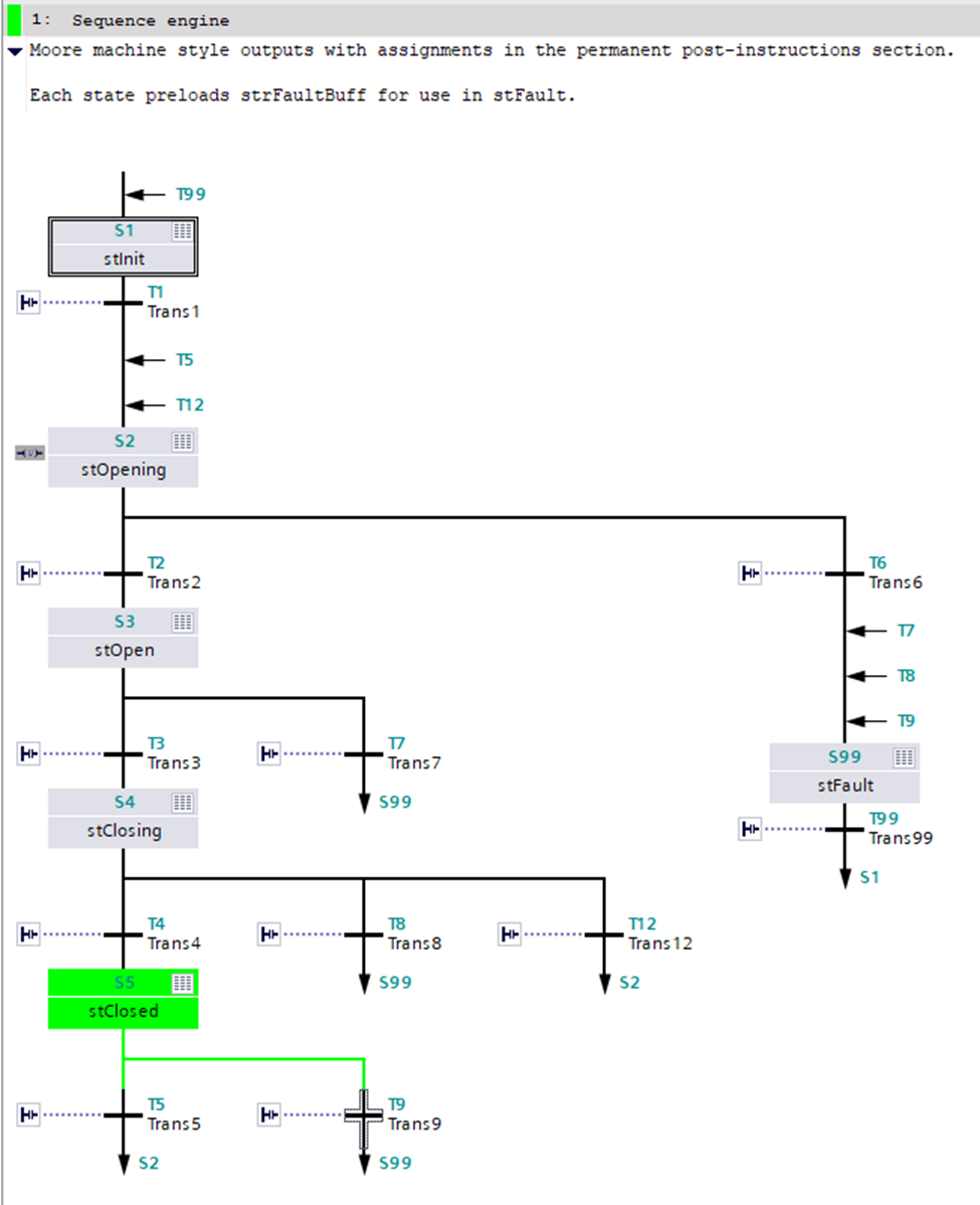
Figure 1: Graphical code for the motor starter sequencer showing all states and transitions.
Tech Tip: SFC may be described as a token-based system. A single token is born in the initial step. This special state is indicated by the double outline surrounding S1. This token is passed from state to state via a gate. For example, in Figure 1, the token is in S5. It may be passed to either S2 or S99 via gate T5 or T9, respectively.
State Descriptions
The states were introduced in the previous articles. They are described here for convenience:
-
stOpen: The motor starter is in an inactive state with no power applied to the contactor’s coil. The UDFB will enter a fault state if the motor starter unexpectedly closes for longer than timDebounce. This detects the unsafe practice of a technician forcing the motor starter’s armature. This is a dangerous practice as it defeats all safety aspect of the machine (don’t do it).
-
stClosing: The motor starter’s contactor is transitioning from an open to a physically closed state. The UDFB will enter a fault state if the contacts fail to close within timTransition.
-
stClosed: The motor starter is running. The UDFB will enter a fault state if the sensor signal is momentarily lost for a period longer than timDebounce. This fault could be caused by a loose drive wire leading to the motor starter or the feedback line. It could also be caused by an overload event which would trip the motor starter via the thermal overload block.
-
stOpening: The motor starter’s contactor is transitioning from a closed to an open state. A fault is triggered if the contacts do not open within timTransition as this implies that the primary or interposing relay contacts have been welded together.
-
stFault: The motor starter is in a fault condition. It will be released when the enable signal is disabled and the reset button is pressed.
Moore Machine Pattern
For simplicity and to reduce writing, a Moore machine style was selected allowing the output logic to be split from the sequencer. Here, the term Moore implies that the outputs are entirely dependent on the state of the machine.
Note that each function block contains several sections as shown in Figure 2. This includes the pre-instructions, sequences, and the post-instructions. Think of these as three sequential instruction sets that are executed in order for every cycle scan.
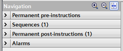
Figure 2: GRAPH function block navigation.
Continuing with our previous motor starter examples, there are four Boolean outputs. We are free to drive them from the sequences section or the post-instructions. All things being equal, the results are the same. However, even in this simple program, we have a problem as driving outputs from within the sequencer requires us to maintain variables in six different locations (one assignment per state). The chances of an error are high.
An alternative is to use the Moore style (Figure 3) where we define the outputs based on the state of the machine. In this example we see xValid and xCoilDrive are set.

Figure 3: The Moore machine outputs are set in the post-instruction section.
Tech Tip: As a rule of thumb, if you find yourself driving the same tag from multiple locations, ask if there is a better way. In this example, memory locations such as xValid are driven from a single location. This significantly reduces the chance of missing or incorrectly setting an output.
Handling Fault Strings
As shown in the previous installments, we will generate an error message upon entering the fault state. For example, if the contactor fails to open, we enter the fault state and send “Failed to open, welded contacts?” on strFault.
By definition, we are describing a sequence of events that happens on the state transitions. This is a Mealy-like operation which conflicts with our Moore-based outputs.
Functional but Clumsy Solution
As my first step, I added additional states in the path leading to stFault (S99). In each state I wrote the fault condition to strFault. This worked but cluttered the sequencer with four additional states and four additional transitions.
Simplified Solution Using a Buffer
A more effective solution is to add a temporary buffer:
-
Upon entering the state such as stClosed, the fault condition text is written to strFaultBuff as shown in Figure 4.
-
Normally, this buffer is not used.
-
However, if the fault state is entered, the buffer is transferred to the strFault output as shown in Figure 5.
Note that this pre-fault assignment streamlines the code by eliminating four states and four transitions. The result as shown in Figure 1 is streamlines and relatively easy to follow.

Figure 4: The failure string is preemptively moved to a buffer.

Figure 5: The graphical code showing strFaultBuff being transferred strFault.
Tech Tip: Trust but verify. We want the strFault to be available at the rising edge of the xFault. This was verified using a simple S_MOVE function initiated by positive-edge trigger. Both xFault and strFault appear to be available in the same scan cycle.
Parting Thoughts
Those Moore and Mealy FSM models we learned back in digital logic class are still with us. They provide a valuable framework that allows us to quickly describe when assignments are made.
It also allows us to see the tension in the featured code. By declaring Moore-based outputs we abandoned some of the Siemens Sequencer’s flexibility. At the same time, I would argue we gain program clarity using the best of both worlds. The sequencer’s green debugging is easy to follow, as are the post-instruction ladder assignments.
Is this a reasonable trade-off? How would you implement the FSM?
Best wishes,
APDahlen
 Continue Exploring Industrial Control Systems
If this discussion was helpful, you may also want to explore:
 DigiKey Navigation
- Full Catalog: Industrial Control & Automation
 Related Foundational Articles
- Should PLC language match technician skill?
- Teardown of a SICK Reflex Array Sensor
- Light Curtain Teardown; Inside the Banner EZ-Screen LP
About This Author
Aaron Dahlen, LCDR USCG (Ret.), is a Senior Applications Engineer at DigiKey in Thief River Falls. His background in electronics and industrial automation was shaped by a 27-year military career as both technician and engineer, followed by over a decade of teaching.
Dahlen holds an MSEE from Minnesota State University, Mankato. He has taught in an ABET-accredited electrical engineering program, served as coordinator of an electronic engineering technology program, and instructed military technicians in component-level repair.
Today, he has returned to his home in northern Minnesota, completing a decades-long journey that began with a search for capacitors. Read his story here.