This engineering brief demonstrates the PIC16 Configurable Logic Block (CLB) by controlling the stepper motor as shown in Figure 1. The CLB allows us to consolidate and absorb the gate-level (74-series) glue logic that often surrounds a microcontroller. The result is a smaller footprint, leaner BOM, and lower overall cost.
-
The CLB fabric operates independently of the PIC16 microcontroller core.
-
Half stepping control is used for the stepper motor.
-
The motor is controlled via a direction and an enable pushbutton.
-
The motor operates at fixed speed as programmed by the user.
-
The digital logic is coded in Verilog. That’s not a typo, Verilog is now on the PIC16.
This project is focused on the Verilog design capabilities of the PIC16F13145. Download the project here:Stepper.X.zip (596.1 KB)
Prerequisite Material
In a previous post we explored a seed project to get us started with the Microchip PIC16 CLB. Please review the article before continuing as it presents the prerequisite material such as I/O pin configurations and connecting simple logic blocks using the MPLAB MCC tools.
Don’t Confuse Microchip’s CLB with the CLC
Microchip’s Configurable Logic Block (CLB) is easily confused with the PIC’s Configurable Logic Cells (CLC). This is understandable, as both offer digital logic functionality, and both are found on select PIC16 family members.
It’s helpful to think of PIC16 digital logic peripherals in terms of relative size and capability:
-
Little Logic: CLC Introduction showing how to configure the CLC into a classic 555 timer.
-
Big Logic: CLB Introduction presenting a seed project. In a moment we will introduce a stepper motor example.
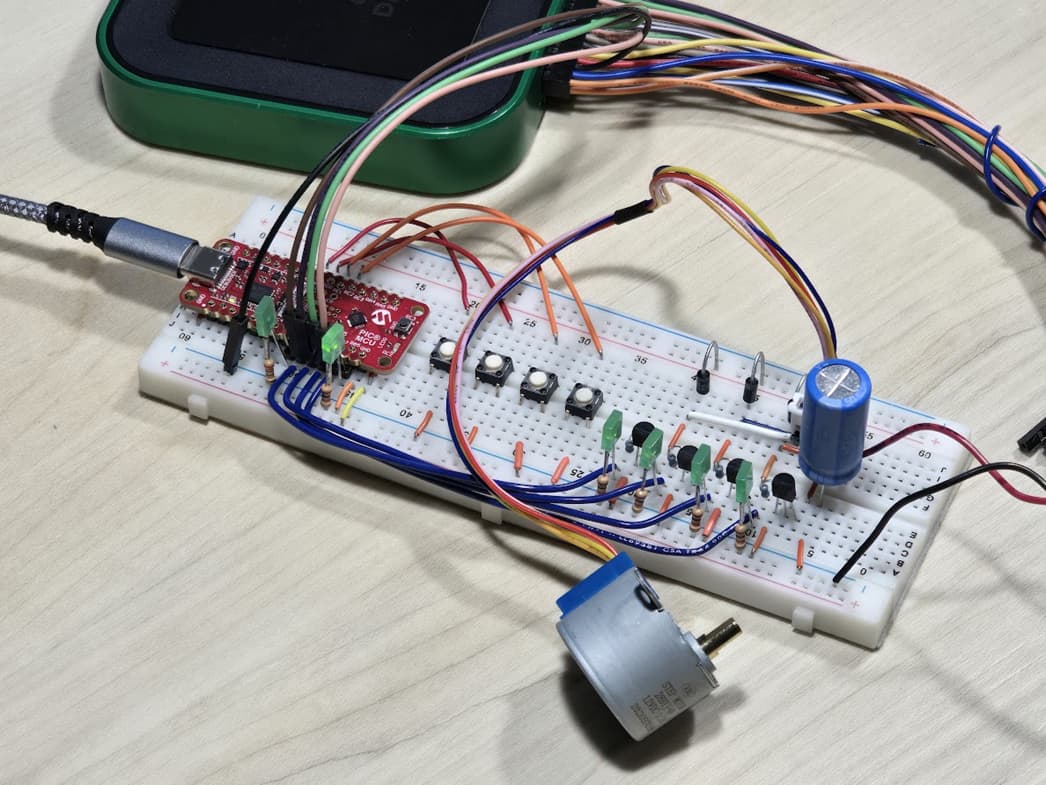
Figure 1: Stepper motor drive used in the demo project.
Do not cross the 3.3 VDC supply with the 12 VDC.
In Figure 1 we see that the breadboard’s upper rail is connected directly to 12 VDC. Do not connect the PIC’s pins to this rail. You will smoke the PIC if you do.
I’ve been there and can tell you that it happens very quickly. The PIC explodes and things only get worse when the USB port in your PC burns out. It’s a costly lesson you will not forget.
Parts Required to Duplicate the Experiment
The stepper motor demonstration shown in Figure 1 was constructed using the following components (DigiKey links included for core components):
-
Microchip EV06M52A curiosity evaluation board for the PIC16F13145 microcontroller
-
Motor winding flyback diode
-
2N3904 transistor
-
1 kΩ resistor in series with the base of each transistor
-
LED with resistor as described in this logic probe substitution article
-
Power supply decoupling capacitor e.g., 1000 uF 25 VDC
-
Breadboard, wire, and jumpers
-
12 VDC power supply not shown
Circuit Construction
Be sure to review the prerequisite article before attempting construction. This will establish a baseline to simplify construction and troubleshooting. From there, you should have no problems constructing the circuit. Use the Figure 3 schematic as a guide along with the pictures included in Figure 1 and 2.
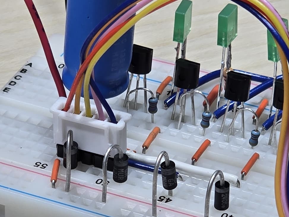
Figure 2: A flyback diode is included across each motor winding. A series resistor is included for each transistor base.
Tech Tip: Don’t forget to place a flyback diode in parallel with each motor winding. Failure to include the diodes will result in high voltage spikes that will destroy the 2N3904 transistors. The diodes are prominently shown connected to the breadboard rail in Figure 2.
The transistor base current limiting resistors are visible in the background.

Figure 3: Schematic for the stepper motor project featuring discrete NPN transistors for the motor drive.
Why was Verilog used for this demonstration project?
Verilog was chosen as it is fast and easy to troubleshoot when compared to the gate-level representations. In this instance, Verilog eliminates the need to develop the Karnaugh maps for the state-next as well as the output logic. What previously took hours can be done in minutes.
At the same time, I don’t want to rob learners of the learning opportunity to design the gate-level solution. With Verilog, I can quickly show you the end results and then suggest you take the time to manually construct the state machine from the ground up.
On a personal note: Verilog provides a wow factor. I never thought I would program a PIC16 in Verilog when I started programming nearly 25 years ago. Then again, I was writing in assembler.
Verilog Programming of the Stepper Motor Control Logic
The top-level control logic description is included as Figure 4. It includes two sections:
-
State: This module accepts the enable and direction input from the pushbuttons. It maintains the 3-bit state register controlling the half stepping sequence. The code is included as Listing 1. There we can see that this module operates as a 3-bit up down counter.
-
Stepper_Outputs: This module accepts the 3-bit state and produces the required output signals as shown in Figure 5. The code is included as Listing 2. The module operates as a decoder with the core operation implemented as a lookup table.
The modules were constructed independently to simplify troubleshooting. The state module was constructed first. It was temporarily connected to the PIC outputs, and the operation was verified using LEDs.
Note that the stepper motor project consumes approximately 50% of the digital logic fabric.

Figure 4: Top level logic description showing two Verilog modules.
module State(
    input CLK, enable, dir,
    output step_val_2, step_val_1, step_val_0
);

    reg [2:0] step_val;

    assign {step_val_2, step_val_1, step_val_0} = step_val;

    always @(posedge CLK) begin
        if (enable) begin
            if (dir == 1'b0) begin
                step_val <= step_val + 3'b001;   // forward
            end else begin
                step_val <= step_val - 3'b001;   // reverse
            end
        end
    end
endmodule
Listing 1: Verilog code for the state module.

Figure 5: Half-stepping drive waveforms for the stepping motor with eight discrete outputs.
module StepperOutputs(
    input  CLK,
    input  step_val_2, step_val_1, step_val_0,
    output out_3, out_2, out_1, out_0
);

    reg [3:0] step_val;

    assign {out_3, out_2, out_1, out_0} = step_val;

    always @(posedge CLK) begin
        case ({step_val_2, step_val_1, step_val_0})
            3'b000: step_val <= 4'b1000;
            3'b001: step_val <= 4'b1100;
            3'b010: step_val <= 4'b0100;
            3'b011: step_val <= 4'b0110;
            3'b100: step_val <= 4'b0010;
            3'b101: step_val <= 4'b0011;
            3'b110: step_val <= 4'b0001;
            3'b111: step_val <= 4'b1001;
            default: step_val <= 4'b0000;
        endcase
    end
endmodule
Listing 2: Verilog code for the stepper output module
Parting Thoughts
This stepper motor project is a yardstick for the PIC16’s CLB. We now know what to expect from the PIC16 in terms of capabilities, programming style, and ease of use. This baseline allows us to compare the PIC16 against classic 74-series logic as well as other HDL tools.
Best wishes,
APDahlen
Related Articles by this Author
If you enjoyed this article, you may also find these related articles helpful:
-
Tips for using the MCC tool: Preventing Microchip’s MCC Melody from Overwriting Your Code
-
Explore the struct from RC servo robot arm: What is a struct?
-
See a PIC16 used in an industrial application: Light Curtain Teardown; Inside the Banner EZ-Screen LP
About This Author
Aaron Dahlen, LCDR USCG (Ret.), serves as an application engineer at DigiKey. He has a unique electronics and automation foundation built over a 27-year military career as a technician and engineer which was further enhanced by 12 years of teaching (interwoven). With an MSEE degree from Minnesota State University, Mankato, Dahlen has taught in an ABET-accredited EE program, served as the program coordinator for an EET program, and taught component-level repair to military electronics technicians.
Dahlen has returned to his Northern Minnesota home, completing a decades-long journey that began as a search for capacitors. Read his story here.