A common question when looking at ceramic capacitors is what do the temperature coefficient numbers/letters mean? These numbers will generally break down to a temperature range and the variation in capacitance over that specific range. The first thing you need to understand with what standard and class you are looking at. These are split between the International Electrotechnical Commission (IEC) and the Electronic Industries Alliance (EIA)
Here is a chart on the different classes and definitions:
| IEC/EN 603841 & IEC/EN 60384-8/9/21/22 |
EIA RS-198 |
|---|---|
| Class 1 ceramic caps offer high stability and low losses for resonant circuit applications | Class I ceramic caps offer high stability and low losses for resonant circuit applications |
| Class 2 ceramic capacitors offer high volumetric efficiency for smoothing, by-pass, coupling and decoupling applications | Class II (or written class 2) ceramic capacitors offer high volumetric efficiency with change of capacitance lower than −15% to +15% and a temperature range greater than −55 °C to +125 °C, for smoothing, by-pass, coupling and decoupling applications |
| Class 3 ceramic capacitors are barrier layer capacitors which are not standardized anymore | Class III (or written class 3) ceramic capacitors offer higher volumetric efficiency than EIA class II and typical change of capacitance by −22% to +56% over a lower temperature range of 10 °C to 55 °C. They can be substituted with EIA class 2- Y5U/Y5V or Z5U/Z5V capacitors |
| Class IV (or written class 4) ceramic capacitors are barrier layer capacitors which are not standardized anymore |
With class definitions understood you can look how the temperature coefficients break down.
Class 1 per EIA-RS-198
| Temperature coefficient α 10-6 /K Letter code |
Multiplier of the temperature coefficient Number code |
Tolerance of the temperature coefficient Letter code |
|---|---|---|
| C: 0.0 | 0: -1 | G: ± 30 |
| B: 0.3 | 1: -10 | H ± 60 |
| L: 0.8 | 2: −100 | J: ±120 |
| A: 0.9 | 3: −1000 | K: ±250 |
| M: 1.0 | 4: +1 | L: ±500 |
| P: 1.5 | 6: +10 | M: ±1000 |
| R: 2.2 | 7: +100 | N: ±2500 |
| S: 3.3 | 8: +1000 | |
| T: 4.7 | ||
| V: 5.6 | ||
| U: 7.5 |
Class 1 per IEC/EN 60384-8/21 and EIA-RS-198
| Ceramic names | Temperature coefficient α 10-6 /K | α-Tolerance 10-6 /K | Sub-class | IEC/ EN- letter code | EIA letter code |
|---|---|---|---|---|---|
| P100 | 100 | ±30 | 1B | AG | M7G |
| NP0 | 0 | ±30 | 1B | CG | C0G |
| N33 | −33 | ±30 | 1B | HG | H2G |
| N75 | −75 | ±30 | 1B | LG | L2G |
| N150 | −150 | ±60 | 1B | PH | P2H |
| N220 | −220 | ±60 | 1B | RH | R2H |
| N330 | −330 | ±60 | 1B | SH | S2H |
| N470 | −470 | ±60 | 1B | TH | T2H |
| N750 | −750 | ±120 | 1B | UJ | U2J |
| N1000 | −1000 | ±250 | 1F | QK | Q3K |
| N1500 | −1500 | ±250 | 1F | VK | P3K |
Looking at these charts you see, an “NP0” capacitor with EIA code “C0G” will have 0 drift, with a tolerance of ±30 ppm/K, while an “N1500” with the code “P3K” will have −1500 ppm/K drift, with a maximum tolerance of ±250 ppm/°C.
Note that the IEC and EIA capacitor codes are industry capacitor codes and not the same as military capacitor codes.
Class 2 per EIA RS-198
| Letter Code for Low Temp | Number Code for High Temp | Letter code for change of capacitance over the temp range |
|---|---|---|
| X = −55 °C (−67 °F) | 4 = +65 °C (+149 °F) | P = ±10% |
| Y = −30 °C (−22 °F) | 5 = +85 °C (+185 °F) | R = ±15% |
| Z = +10 °C (+50 °F) | 6 = +105 °C (+221 °F) | S = ±22% |
| 7 = +125 °C (+257 °F) | T = +22/−33% | |
| 8 = +150 °C (+302 °F) | U = +22/−56% | |
| 9 = +200 °C (+392 °F) | V = +22/−82% |
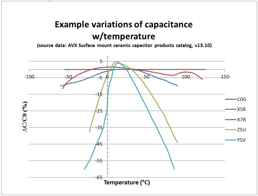
For instance, a Z5U capacitor will operate from +10 °C to +85 °C with a capacitance change of at most +22% to −56%. An X7R capacitor will operate from −55 °C to +125 °C with a capacitance change of at most ±15%.
Here are some common Class 2 configurations:
- X8R (−55/+150, ΔC/C0 = ±15%),
- X7R (−55/+125 °C, ΔC/C0 = ±15%),
- X6R (−55/+105 °C, ΔC/C0 = ±15%),
- X5R (−55/+85 °C, ΔC/C0 = ±15%),
- X7S (−55/+125, ΔC/C0 = ±22%),
- Z5U (+10/+85 °C, ΔC/C0 = +22/−56%),
- Y5V (−30/+85 °C, ΔC/C0 = +22/−82%),
Class 2 per IEC/EN 60384-9/22
| Code for capacitance change | Max capacitance change ΔC/C0 at U = 0 |
Max capacitance change ΔC/C0 at U = UN |
Code for temp range | Temp Range |
|---|---|---|---|---|
| 2B | ±10% | +10/−15% | 1 | −55 … +125 °C |
| 2C | ±20% | +20/−30% | 2 | −55 … +85 °C |
| 2D | +20/−30% | +20/−40% | 3 | −40 … +85 °C |
| 2E | +22/−56% | +22/−70% | 4 | −25 … +85 °C |
| 2F | +30/−80% | +30/−90% | 5 | (-10 … +70) °C |
| 2R | ±15% | − | 6 | +10 … +85 °C |
| 2X | ±15% | +15/−25% | - | - |
In some cases it is possible to translate the EIA code into the IEC/EN code. Slight variations can occur, but normally are tolerable.
- X7R correlates with 2X1
- Z5U correlates with 2E6
- Y5V similar to 2F4, aberration: ΔC/C0 = +30/−80% instead of +30/−82%
- X7S similar to 2C1, aberration: ΔC/C0 = ±20% instead of ±22%
- X8R no IEC/EN code available